
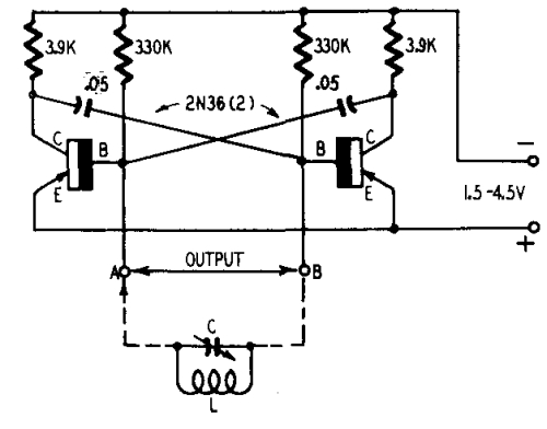
LED Torch Uses Blocking Oscillator

The circuit utilizes a two-transistor configuration to create a blocking oscillator, which is a type of oscillator that generates a square wave output. This output is used to drive an LED, providing illumination. The oscillator's design allows it to operate efficiently with a low input voltage, making it suitable for battery-powered applications.
In this configuration, one transistor acts as a switch, while the other serves as a feedback element. When the circuit is powered on, the initial current through the first transistor causes it to turn on, allowing current to flow through the second transistor. This feedback loop continues until the energy stored in the circuit's inductor is released, generating a high voltage pulse that powers the LED.
The inherent current limit of the circuit is crucial for preventing damage to the components. By carefully selecting the resistor values and the characteristics of the transistors, the circuit ensures that the current remains within safe limits while still providing adequate brightness from the LED.
Additional components may include a small inductor, which is essential for energy storage and voltage stepping, as well as capacitors to stabilize the circuit and filter out any noise. The overall design is compact and efficient, making it ideal for portable lighting solutions. The simplicity of the circuit allows for easy assembly and troubleshooting, making it accessible for both beginners and experienced electronics enthusiasts.This simple LED torch is driven by a 2-transistor blocking oscillator which steps up the voltage from a 1.5V cell. It relies on the inherent current limit.. 🔗 External reference
Related Circuits
Transistors are increasingly being utilized in various applications. Many circuits employing transistors have been developed based on previous designs that used vacuum tubes. The following chapters present unique applications that leverage the advantageous properties of transistors. The described circuits...
The circuit utilizes two quad voltage comparators (LM339) to illuminate a series of eight LEDs that indicate volume levels. Each of the eight comparators is biased at increasing voltages determined by a voltage divider, allowing the lower right LED...

The circuit operates as a unijunction transistor relaxation oscillator. The base of the lower PNP transistor is biased at approximately half of the supply voltage. As the 100pF capacitor charges through the 1GΩ resistor, the base of the upper...

The circuit is based on an LM3914N bar graph display driver device (IC1), which can be used to drive up to ten LEDs. This is connected so that with OV12 at the input only the first LED indicator switches...
The crystal is positioned in the feedback path of a Pierce oscillator, situated between the base and collector of transistor Q1, with a 2.5 mH RF choke replacing the tuned collector circuit. The oscillator operates within a frequency range...
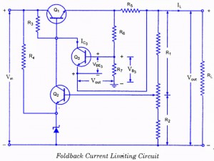
If the load resistance (RL) is reduced or the load terminals are accidentally shorted, a very large load current will flow, potentially damaging the pass transistor (Q1), diode, or other components. Fuse protection may not be sufficient, as the...