
Dicing With LEDs

The electronic dice circuit utilizes a 4060 digital counter as its core component, integrating both the counting and oscillation functions. The oscillator is configured using resistors R7 and R8 and capacitor C7, generating a stable clock signal necessary for the counter's operation. The output from the counter is carefully managed to ensure that only six states are represented, aligning with the traditional six faces of a die. The reset mechanism, facilitated by diodes D11 and D12, along with resistor R6, ensures that the counter does not exceed the desired six states, maintaining the integrity of the dice function.
The LED display is designed to reflect the traditional layout of a die, with careful consideration of the LED connections to ensure that two LEDs illuminate simultaneously for all states except for the "1." This design not only simplifies the circuit but also optimizes power consumption, making it suitable for battery operation. The use of low-current LEDs ensures that the circuit remains energy-efficient while still providing adequate brightness for visibility.
The inclusion of diodes D8 to D10 and transistor T1 is critical for accurately displaying the two and three-spot configurations, which require diagonal arrangements. This attention to detail enhances the realism of the electronic die, making it a more engaging and functional device for users. The activation switch S1 serves a dual purpose: it initiates the counting process while also ensuring that the circuit remains dormant when not in use, thus preserving battery life.
Overall, this electronic dice circuit exemplifies a well-thought-out design that combines functionality with efficiency, making it an excellent project for DIY electronics enthusiasts. The straightforward assembly process, along with the compact design, allows for easy integration into various applications, providing a reliable and entertaining alternative to traditional dice.Every self-respecting DIYer makes his own electronic dice with LEDs as spots. Then you don`t have to throw the dice anymore just push the button. The electronics also ensures that nobody can try to improve his luck by fiddling with the dice. Too bad for sore losers! This circuit proves that an electronic die built using standard components can be made quite compact. The key component of here is a type 4060 digital counter (IC1). This IC has an integrated oscillator stage, so only two resistors (R7 and R8) and a capacitor (C7) are necessary to generate the clock signal. The clock signal is divided by various factors by the internal digital circuitry of the IC. The division factors are designated by CT` in the IC drawing symbol. For instance, the signal on the CT3 output (pin 7) is a square wave with a frequency equal to the clock frequency divided by 23 (8).
The clock signal is divided by 24 (16) on the CT4 output, by 25 (32) on the CT5 output, and so on. This means the output signals form a binary number that Dicing with LEDs counts upwards, which is naturally what a counter does. Of course, a die has only six possible values marked on the six sides of a cube. This means that at least three bits (the first three outputs) of the counter are necessary to drive a display.
Eight different counter states (23) can be represented with three bits, but in this case the counter must be restricted to six states. To make sure this happens, D11, D12 and R6 are used to reset the counter to its initial state when it reaches the seventh state, which means when it reaches a binary count of 110.
When this happens, pins 4 and 5 of the IC are both logic 1` (high level), which causes a logic 1` to be applied to pin 12 via resistor R6. This causes the counter to be reset, which is what we want. The display consists of seven LEDs arranged in the same pattern as the usual markings on a normal die.
This arrangement is shown in the schematic diagram. Before you begin thinking about the proper logical connections between the LEDs and the counter outputs, you can start by noting that except for the 1` state there will always be two LEDs lit up at the same time. This means that only four distinct indications are necessary, instead of seven (with a total of seven LEDs).
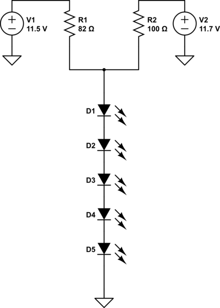
Another advantage of this is that the current consumption can be reduced by connecting pairs of LEDs in series. Resistors R1 R4 limit the current through the LEDs to approximately 2 mA. This means you have to use low-current LEDs. They are nice and bright at a current of 2 mA. Resistor R3 has a higher value because only one LED is driven via it. For convenience, the circuit is dimensioned based on using a 9-V battery. The current consumption of the circuit depends on the number of LEDs that are illuminated, and with our prototype it varied over a range of approximately 2.
5 mA to 6. 5 mA. The LEDs still produce enough light even when the supply voltage is as low as 6 V, but this depends strongly on the characteristics of the low-current LEDs used in the circuit. Diodes D8 D10 and transistor T1 are necessary to enable all the states of a normal die to be shown. By that, we primarily mean the states with two or three spots, which must be located diagonally. For readers who want to delve more deeply into the design, the following table shows the six different binary states, which LEDs are lit up for each state, and the number of spots shown by the die.
The die is operated by switch S1. In the quiescent state, the break contact of S1 is closed and the oscillator is stopped because the input of the oscillator stage is connected to ground via the switch. When S1 is pressed, the oscillator starts running and causes the states of the LEDs to change at a rate of 1 kHz, which is too fast to follow with the naked eye.
This high frequency ensures that the state of the die is purely random when S1 is released, so there is no regularity or pattern in the results. The circuit can be assembled on a small piece of perforated prototyping board. Fit the LEDs in exactly the same pattern as shown in the schematic diagram, since otherwise the spot patterns will not correspond to a real die.
When you have assembled the circuit board, fit it in a plastic enclosure along with a 9-V battery to provide power. 🔗 External reference
Related Circuits
A series of LEDs is intended to display at two brightness levels, and there is uncertainty regarding the proper wiring. This setup is for additional running lights and brake lights on a bicycle. When using the series LED calculator,...
This indicator shows through a dual-LED see if a fuse is intact. The module is designed for 230 V AC. The green LED illuminates when the fuse is still good, the red lights when the fuse is broken. Perhaps...
In the circuit below, a quad voltage comparator (LM339) is used as a simple bar graph meter to indicate the charge condition of a 12 volt, lead acid battery. A 5 volt reference voltage is connected to each of...
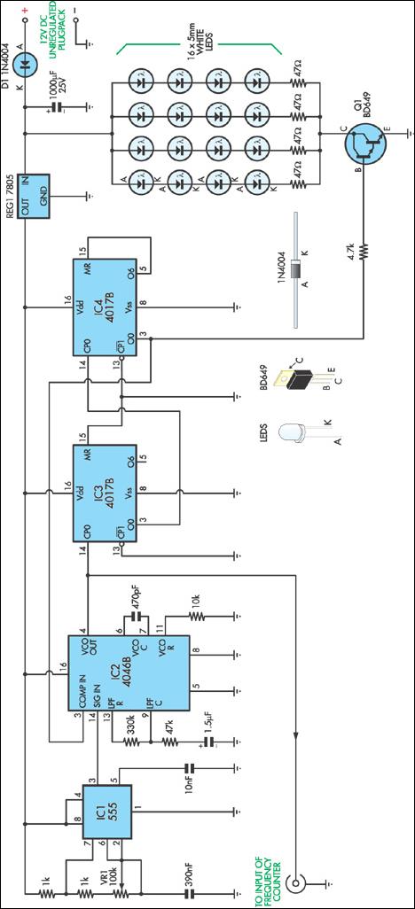
This stroboscope circuit employs 16 high-brightness white LEDs housed in a torch and provides a signal output to a frequency counter for rev counter display. The circuit utilizes IC1, a 555 astable multivibrator, which generates a signal for IC2,...
The following circuit illustrates a Dancing LEDs electronic circuit diagram. This circuit is based on the LM358 integrated circuit. Features: IC1A amplifies the signal. The Dancing LEDs circuit utilizes the LM358 operational amplifier to create a visually appealing light display....
This circuit operates two LED strips in pulsing mode, where one LED strip transitions from an off state to gradually lighting up, then dimming, while the other LED strip performs the opposite action. Each strip can consist of 2...