
555 Timer as an A/D converter

The 555 timer IC is a versatile device widely used in various timing applications. In this circuit configuration, the timer operates in a monostable mode, producing a pulse output based on the input voltage and the capacitor's charge. The pulse width can be finely tuned by altering the input voltage, allowing for precise voltage measurements.
The calibration process is critical for ensuring accurate readings. By establishing a reference voltage and calculating the coefficient, the circuit can reliably convert pulse counts into voltage values. The relationship between the pulse width and the input voltage is leveraged to create a linear approximation of the voltage measurement, making it suitable for integration with microcontroller platforms like the Basic Stamp.
The implementation of debug lines is essential for monitoring performance during the calibration process. It facilitates real-time adjustments and ensures that the system operates within its specified accuracy range. Furthermore, the limitations regarding voltage measurement below 5 volts must be accounted for, as they may affect the applicability of this circuit in lower voltage environments.
Overall, this circuit exemplifies a practical application of the 555 timer in voltage measurement, demonstrating its effectiveness and reliability when properly calibrated and utilized within its operational parameters.The 555 timer will put out positive pulses. The pulse width is inversely proportional to the difference in voltage between the voltage at "ANALOG IN" and the voltage of the 4. 7uF capacitor(let`s say 2. 5 volts). To calibrate this circuit, hook it up to a Basic Stamp measuring positive pulses, and give the circuit a known voltage.
Let`s say you get the number 2092 when you give the circuit 15 volts. Your coefficient is 2092 * (15 - 2. 5) = 26150. Now you are ready to measure voltage with your Basic Stamp. Use the formula: voltage = 26150/pulse + 2. 5. You will have to modify this to work within the limits of the Basic Stamp`s math. The accuracy of this circuit rivals many digital voltmeters within the range I tested it (6 volts to 18 volts), about the same as a 10 bit A/D converter. The accuracy will shift with the processor clock and the +5 supply, so it is pretty good. Conversion time is under 1/10 second. Please note it will not measure voltages below 5 volts. Also, check the accuracy of your +5 volts. If it is 5. 2 volts, you will need to use 2. 6 in the formula. `uncomment the debug lines to get pulse value while calibrating loop: `debug cls pulsin 0, 1, w2 `I used pin 0 `debug w2 w1=26150 `This is the coefficient you will need to calibrate.
w4=w1/w2 w3=w4*100 `I am going to get around the integer-only Stamp math. w4=w2*w4 w1=w1-w4*10 `remember the Stamp has left-to-right math w4=w1/w2 w3=w4*10+w3 w4=w2*w4 w1=w1-w4*10 w4=w1/w2 w3=w4+w3 w3=w3+250 `250 is really 2. 5 volts debug w3, "volts * 100" `we get a reading in hundredths of volts goto loop 🔗 External reference
Related Circuits
The preamplifier is straightforward, utilizing a low-noise integrated circuit manufactured by Hewlett Packard, specifically the MGA86563. This device features a noise figure of approximately 2 dB and operates within a frequency range of 0.5 GHz to at least 6...
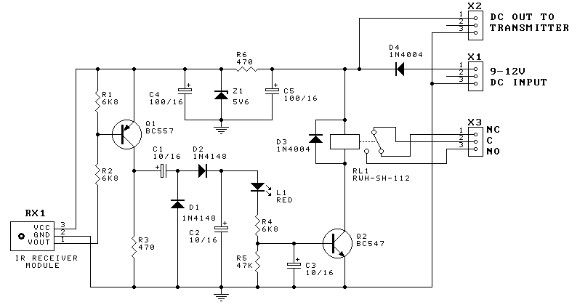
This door minder electronic project is based on a 555 timer circuit and utilizes an infrared (IR) beam to monitor doorways, passageways, or any other designated area. When the IR beam is interrupted, a relay is activated, which can...

The overhaul includes features such as online judge diodes, the ability to test whether transistors are functioning properly, and the capability to assess TTL logic levels or high impedance states. It can output signals at 37 MHz, bar television...

Voltage converter circuit diagram for converting 3 volts to 5 volts using CMOS monolithic ICs MAX660 and MAX667, which functions as a positive voltage regulator. The voltage converter circuit utilizes the MAX660 and MAX667 integrated circuits to step up a...
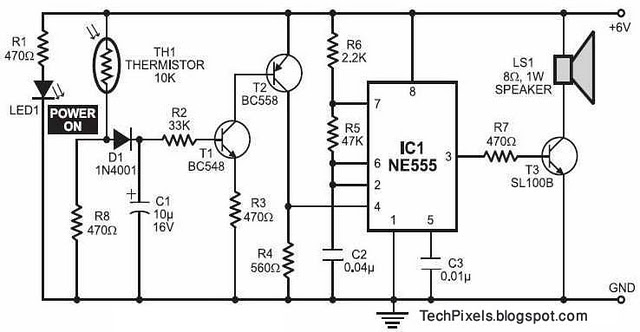
The following circuit illustrates a fire alarm circuit diagram utilizing the NE555 integrated circuit (IC). Features include functioning as a heat sensor and incorporating a 10 kilo-ohm resistor. The fire alarm circuit based on the NE555 IC is designed to...
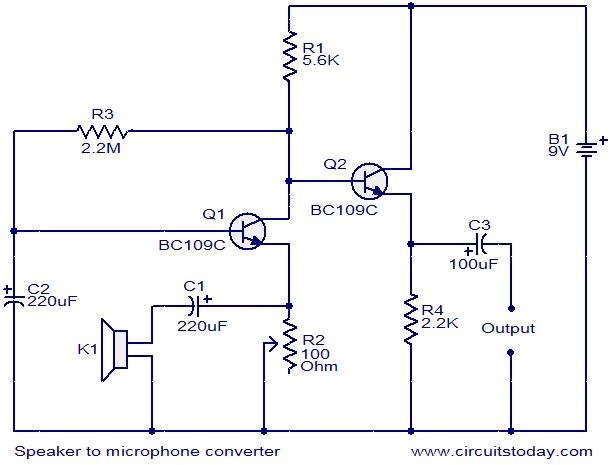
This circuit provides a straightforward method for converting a loudspeaker into a microphone. When sound waves impact the diaphragm of the speaker, fluctuations occur in the coil, generating a small induced voltage that is typically low in magnitude and...