
led flashing circuit

This circuit operates as an astable multivibrator, which is a fundamental configuration for generating square wave signals. The continuous oscillation between the two states is created by the feedback mechanism established through the two transistors, T1 and T2. When one transistor turns on, it drives the other into a cutoff state, creating a rapid switching effect that results in the flashing of the LEDs.
The timing characteristics of the circuit are primarily determined by the values of the resistors and capacitors connected to the transistors. The potentiometer P1 allows for the adjustment of the timing, providing control over the frequency of the LED flashing. A lower resistance or capacitance value will yield a faster oscillation frequency, leading to quicker transitions between the on and off states of the LEDs.
The circuit's design is robust, allowing for the use of various small-signal transistors, such as the BC238, provided that they have similar characteristics to the BC547B. This flexibility in component selection ensures that replacements can be made without significantly affecting circuit performance. However, it is crucial to ensure that both transistors are functioning correctly, as a failure in either component can disrupt the oscillation and diminish the circuit's overall functionality.
The circuit is designed to operate effectively at a nominal voltage of 9 volts, making it suitable for a variety of applications. Lower operating voltages can also be utilized, which may require recalibration of the resistors to maintain the desired flashing frequency. The use of red LEDs is standard in this design, but the circuit can be adapted to accommodate different colors by adjusting the series resistors R1 and R4, which control the current flowing through the LEDs, thus allowing for a range of visual effects based on the selected LED color.It`s state is constantly changing and this change affect the flow of current and voltage and the effect will be visible with the two leds. The speed of the led flasher may be adjusted with potentiometer P1. Being an astable multivibrator, the circuit has no stable state but oscillates continuously between the two states back and forth.
The two transistors T1 and T2 turn and lock each other by turn. The smaller the capacitor value is and the smaller the resistance, the appropriate LED goes out faster, for the benefit of other, who then immediately turns on. The transistors do not necessarily have to be BC547B, you may use BC238 or similar small-signal transistors.
It is recommended to always use the equivalent transistors. If one of the transistors is defective, wrong or have a malfunction, so does this to the full functionality of this circuit. One LED lights up and the other is dimmed. The two flashing led circuit is designed for 9 Volts but it works at lower voltages too. In this design we used red leds but by changing the series resistors R1 and R4 you can also use different LED colors.
🔗 External reference
Related Circuits
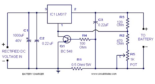
A simple lead-acid battery charger circuit with a diagram and schematic using the IC LM317, which provides the correct battery charging voltage. This lead-acid battery charger should be supplied with an input of 18 volts to the IC. The lead-acid...

Unfortunately, there is no breadboard available for testing; however, modifications can be made to the PCB. The 1K potentiometer has been removed until the strobe functionality can be established. The circuit in question appears to involve a strobe light mechanism,...

Learn how to interface LEDs with the 8051 Microcontroller. Download free source code and circuit diagram of the P89V51RD2 Microcontroller. Interfacing LEDs with the 8051 microcontroller is a fundamental project that serves as an excellent introduction to microcontroller applications. The...

Depending on the external circuit connection, the 555 timer can be configured for various modes such as start delay, trigger delay, multi-harmonic oscillation, and other operational conditions. It functions as a versatile tester with the inclusion of some RC...
There is no PCB since there are no components to mount on one. The object was to create a source of ultraviolet light as fast as possible. The UV tubes I bought from a lighting shop for use with...
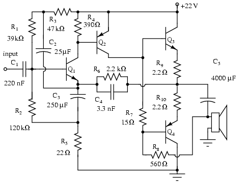
Note that Q3 and Q4 in the figure below are complementary, with Q3 being an NPN transistor and Q4 being a PNP transistor. This circuit is suitable for moderate power audio amplifiers. For a detailed explanation of this circuit,...