
6 Channel Disco Running Lights

The circuit described operates by converting 230 V AC into a regulated +5 V DC supply, which powers the various components of the system. The conversion is typically achieved using a transformer to step down the voltage, followed by a rectifier and a voltage regulator to ensure a stable DC output.
The pulse generator, utilizing an IC 555 timer, generates clock pulses at a defined frequency. This IC is configured in astable mode to produce a continuous square wave output, which serves as the timing signal for the subsequent counting operation. The output from the IC 555 is fed into the IC 4017, a decade counter that counts the incoming pulses. The IC 4017 is designed to produce a high output on one of its ten output pins after counting ten clock pulses, allowing for easy sequential control.
The output pins of the IC 4017 are connected to a series of transistors configured as switches. When the IC 4017 activates a transistor, it allows current to flow through the gate of a triac, effectively triggering it. The triac acts as a switch for the load, which in this case consists of decorative bulbs. The triac can handle AC loads and provides sufficient current to light the bulbs.
The sequence in which the bulbs are turned ON and OFF is controlled by the counting mechanism of the IC 4017, which ensures that after every ten pulses, the next bulb in the sequence is activated. This operation can be designed to alternate the bulbs in a forward and reverse manner, creating a visually appealing lighting effect.
In summary, this circuit combines AC to DC conversion, pulse generation, counting, and triac-based switching to achieve a dynamic lighting control system suitable for decorative applications.From 230 V AC a DC supply of + 5 V is obtained. The power supply is given to the other blocks. The pulse generator at a particular frequency generates the clock pulses. The clock pulses are counted by a counter and gives output after every 10 pulses. The counter drives the transistors, which form the triac firing circuit. The transistors fire the triacs and they provide sufficient current to the load. Decorative bulbs are connected as load for each triac. The bulbs are sequentially turned ON and OFF in forward and reverse way. The IC 555 works as the pulse generator and feeds the clock pulses to IC 4017. IC 4017 is the heart of this circuit. It works as a counter and gives the output after every 10 pulses. It drives the transistors, which in turn fire the triacs. The triac provides sufficient current to the load. 🔗 External reference
Related Circuits
The 555 timer IC is connected for Astable Operation, the clock pulses are fed to the 4017 IC via the 10K resistor. The 4017 is a 10 stage counter, therefore the sequence of the traffic lights is spread over...
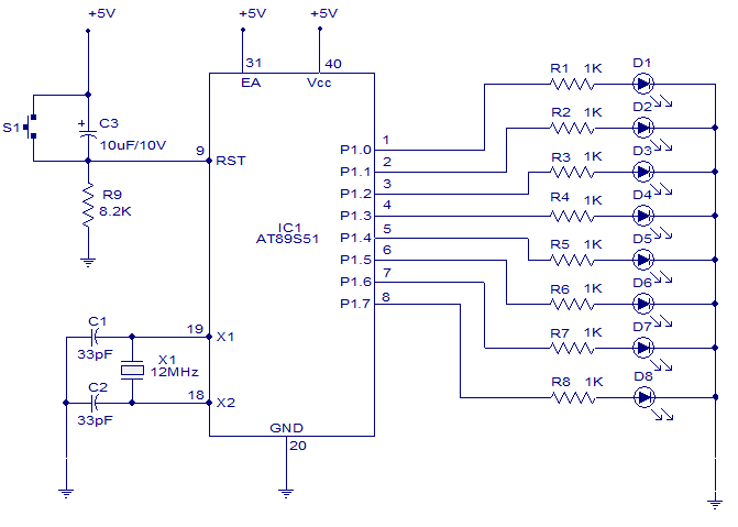
A six-function, eight-channel light chaser utilizing the 8051 microcontroller. The AT89S51, a member of the 8051 family, is employed to produce six distinct lighting sequences. The design incorporates straightforward software and hardware components. The circuit design features the AT89S51 microcontroller...
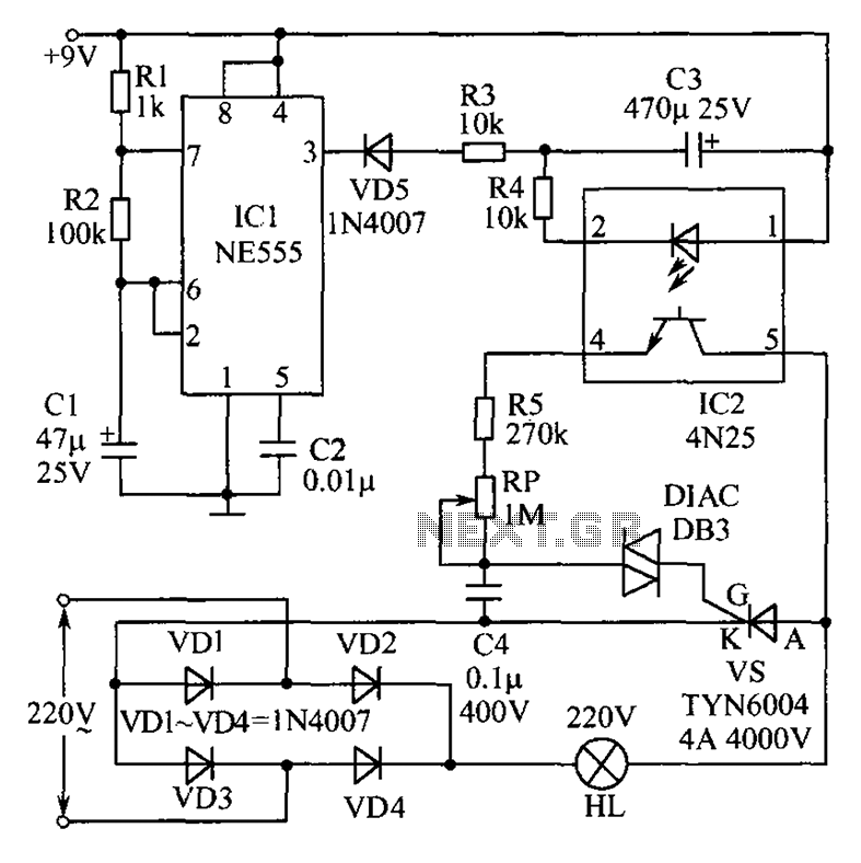
This circuit features an appealing Christmas lights setup. Upon activation, the lights (HL) gradually increase in brightness. Once they reach maximum brightness, they automatically dim, and upon reaching the lowest brightness, they gradually brighten again, creating a smooth transition...
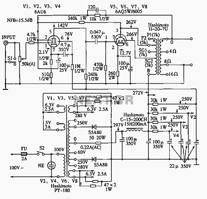
The 6AQ5W / 6005UL four-channel single-ended amplifier circuit is illustrated in the accompanying figure. Only two channels are shown, but it is part of a four-channel system that employs a power transformer for the voltage amplification section. This section...
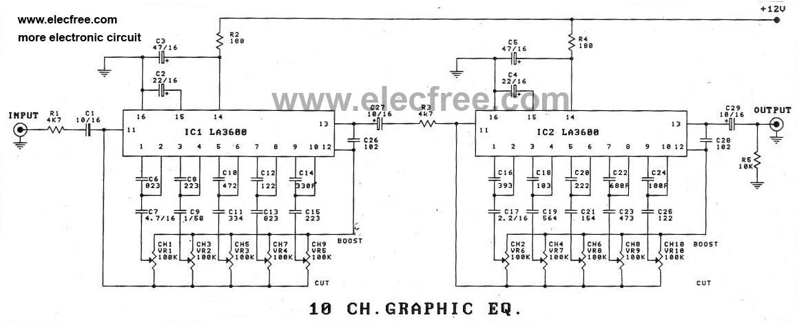
In addition to using the LA3600 IC, a 5-channel graphic equalizer can also be designed as a 10-channel graphic equalizer circuit through appropriate connections. The design of a 10-channel graphic equalizer circuit utilizing the LA3600 integrated circuit (IC) offers enhanced...
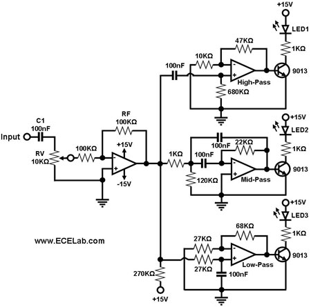
The simple circuit for converting an audio signal. The circuit basically consists of a buffer/amplifier stage and three filter circuits. The audio signal conversion circuit is designed to process audio signals efficiently while maintaining signal integrity. The circuit architecture includes...