
10 Channel Graphic Equalizer by LA3600

The design of a 10-channel graphic equalizer circuit utilizing the LA3600 integrated circuit (IC) offers enhanced audio processing capabilities. This circuit can be constructed by expanding the basic architecture of a 5-channel equalizer to accommodate additional frequency bands, allowing for more precise adjustments of audio signals across a wider spectrum.
The LA3600 is an integrated circuit specifically designed for audio applications, featuring multiple operational amplifiers that facilitate the creation of a graphic equalizer. For a 10-channel configuration, the circuit layout will include two LA3600 chips, each handling five frequency bands. The frequency bands typically correspond to standard audio ranges, such as 31.25 Hz, 62.5 Hz, 125 Hz, 250 Hz, 500 Hz, 1 kHz, 2 kHz, 4 kHz, 8 kHz, and 16 kHz.
The design process begins with selecting the appropriate resistor and capacitor values for each band, which determine the gain and frequency response of the equalizer. Each channel will have its own gain control, allowing users to adjust the amplitude of specific frequency ranges independently. The output of each channel can be fed into a summing amplifier to combine the processed signals into a single output.
Additionally, the circuit will require a power supply that provides the necessary voltage and current for the LA3600 ICs. Proper decoupling capacitors should be placed close to the power pins of the ICs to minimize noise and ensure stable operation. The layout should also consider the placement of components to reduce crosstalk and interference between channels.
Overall, a 10-channel graphic equalizer circuit using the LA3600 IC enhances the audio experience by allowing for fine-tuning of sound characteristics, making it suitable for various applications in audio processing and sound reinforcement systems.In addition to using the LA3600 IC, was the 5 channel graphic equalizer. We can also be designed was the 10 Channel Graphic equalizer circuit. By connection.. 🔗 External reference
Related Circuits
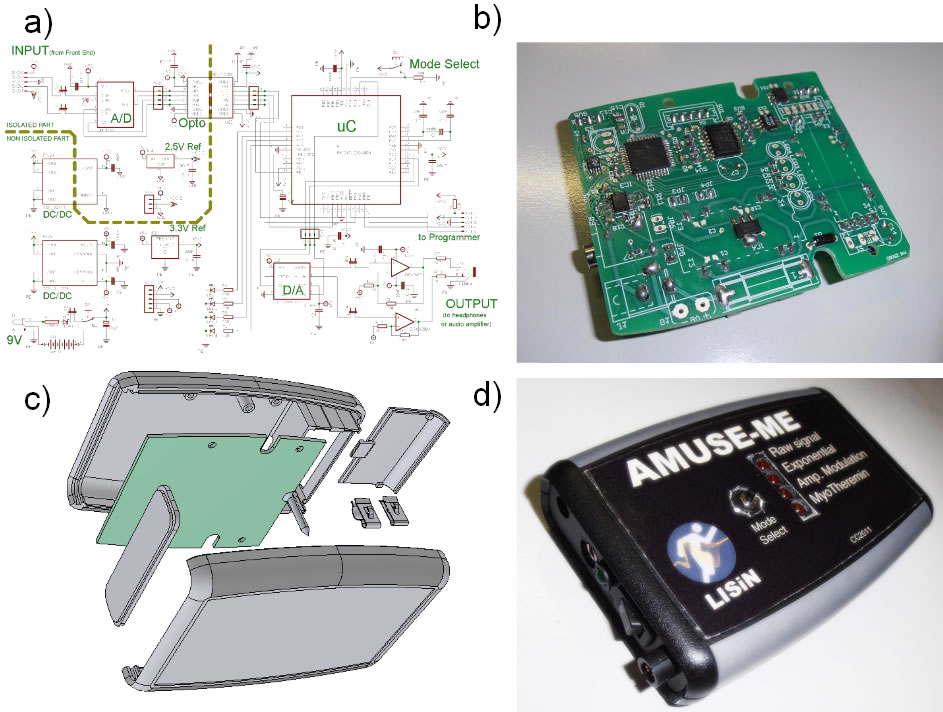
Developers of human-computer interface technologies have recently focused on using bio-electrical signals (such as eye movement and the electrical activity of muscles and brain) as inputs to control devices, aiming to enhance the signal processing capacity of the central...
This small receiver with reduced range (weight 9g, dimensions 32 x 25 mm) is suitable for slow-flyer, little boats, etc. The described receiver is designed for applications requiring lightweight and compact components, making it ideal for slow-flying aircraft and small...
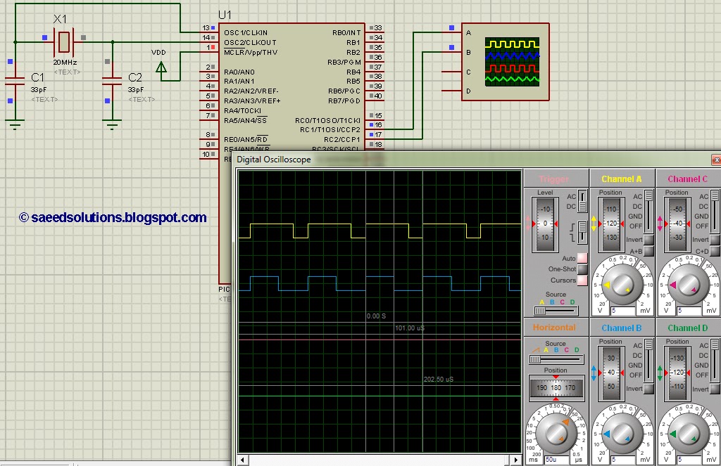
This post addresses the question, "How to create a pulse width modulator using the PIC16F877?" Additionally, the PWM code can be verified using the PIC16 simulator (Proteus). The PIC16F877 microcontroller is widely utilized for creating pulse width modulation (PWM) signals...
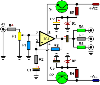
This circuit is designed to amplify and distribute audio signals. The input audio signal is connected to J1 and, after passing through P1, it is buffered and amplified by IC1 for redistribution. It features three outputs that can drive...
This complete high quality, low noise 5-BAND GRAPHIC EQUALIZER circuit is based around Monolithic Linear integrated circuit LA3600 manufactured by SANYO. This circuit is very easy to build and has good Quality. You can use it with Portable component...
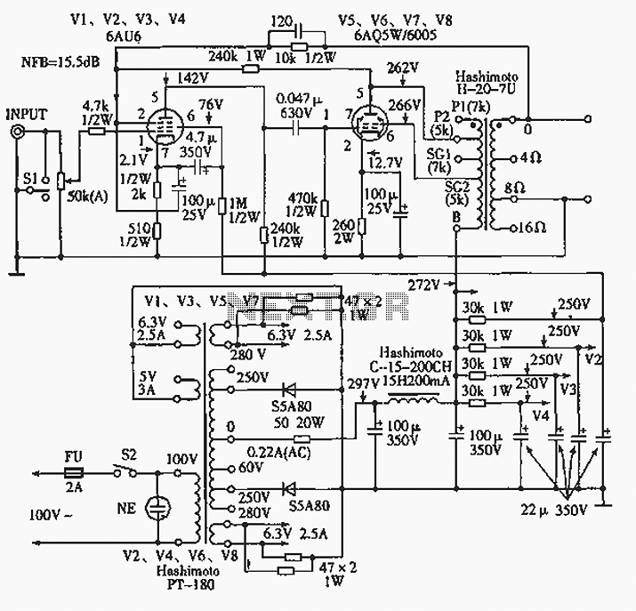
The 6AQ5W / 6005UL four-channel single-ended amplifier circuit is illustrated in the accompanying figure. Only two channels are shown, but it is part of a four-channel system that employs a power transformer for the voltage amplification section. This section...