
6V Light Barrier Sensor Detector

The Light Barrier Sensor Detector Circuit is designed to detect the presence of an object by utilizing a light source and a photodetector. The circuit typically consists of a light-emitting diode (LED) that serves as the light source, and a phototransistor or photodiode that acts as the light detector.
In this configuration, the LED emits light towards the detection area. When an object interrupts the beam of light, the intensity of light received by the phototransistor decreases, triggering a response in the circuit. The single transistor in the circuit functions as an amplifier, enhancing the signal generated by the photodetector when the light barrier is breached.
The potentiometer included in the circuit allows for fine-tuning of the sensitivity of the light detector. By adjusting the potentiometer, one can set the threshold level at which the circuit will respond to the interruption of light. This feature is particularly useful in applications where varying distances or sizes of objects may need to be detected.
The circuit operates at a supply voltage of 6V, which is suitable for low-power applications. The design may include additional components such as resistors and capacitors to stabilize the circuit and filter out noise, ensuring reliable operation.
Overall, this Light Barrier Sensor Detector Circuit is a versatile and efficient solution for object detection in various applications, including automatic doors, security systems, and robotic navigation.The following circuit shows about Light Barrier Sensor Detector Circuit Diagram. Features: single transistor, The potentiometer is adjusted, 6V .. 🔗 External reference
Related Circuits
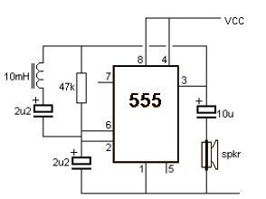
This metal detector electronic project schematic circuit is designed using a simple 555 timer integrated circuit. The schematic circuit requires a few external electronic components. The metal detector circuit utilizes the 555 timer IC in astable mode to generate a...
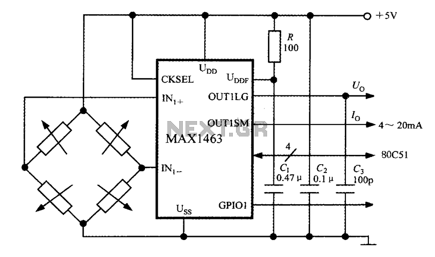
The system consists of a MAX1463 precision pressure detection circuit block diagram. The output voltage from the bridge pressure sensor is connected to the MAX1463 inputs IN1+ and IN1-. Controlled by a CPU, the pressure signal undergoes nonlinear calibration...

1999 Civic Wiring Diagram for Courtesy Lights Manual PDF. The 1999 Civic Wiring Diagram for courtesy lights provides a comprehensive visual representation of the electrical connections and components associated with the vehicle's interior lighting system. This schematic is essential for...
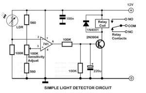
An ambient light sensor circuit is a circuit that utilizes light intensity to perform various applications. An ambient light sensor circuit typically consists of a light-dependent resistor (LDR) or phototransistor that detects the intensity of ambient light. The sensor converts...
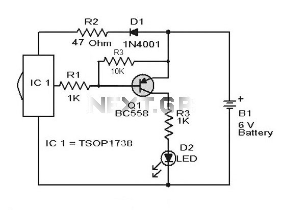
A simple remote control tester circuit with a diagram and schematic using the infrared sensor IC TSOP1738. An LED will blink when infrared waves fall on it, indicating the remote control is functioning. The remote control tester circuit utilizes the...
Using high-beam headlights while driving on the highway can significantly enhance visibility; however, they may pose a blinding risk to other drivers. This straightforward circuit can be integrated into the headlight switch to enable automatic switching between high and...