
Acceleration Monitor using ADXL202 and AVR

The AccelR8 schematic is designed to provide a compact and efficient solution for measuring acceleration using minimal components. The AVR 8515 microcontroller serves as the central processing unit, executing the necessary algorithms to interpret the data received from the ADXL202 accelerometer. The MAX603 voltage regulator ensures that the microcontroller and the accelerometer operate within their specified voltage ranges, providing stable power during operation.
The ADXL202 accelerometer employs a unique micro-machined structure that is sensitive to acceleration forces. This structure, which is part of a capacitor, experiences deflection when subjected to acceleration, allowing for precise measurement of movement along one axis. The output from the ADXL202 is a variable duty-cycle square wave, where the duty cycle correlates directly with the magnitude of the acceleration detected.
The AVR 8515 microcontroller processes this output by measuring the pulse width and period of the square wave signal. By performing calculations based on these measurements, the microcontroller can accurately determine the acceleration value. This calculated data is then formatted for display, enabling users to visualize the acceleration metrics in real-time.
Overall, the schematic design of the AccelR8 demonstrates an effective integration of these three ICs, resulting in a reliable and efficient system for acceleration measurement and analysis. The combination of the AVR 8515, MAX603, and ADXL202 provides a robust platform for applications requiring precise motion detection and monitoring.The schematic show that the AccelR8 only uses 3 IC`s. An AVR 8515 microcontroller do the calculation work and controls the other circuits. An MAX603 controls voltage and power-on/power-off. And the chip that makes it all possible, the ADXL202 from Analog Devices measures the acceleration. This chip is a small wonder. It uses a tiny micro machined polysilicon structure on the silicon wafer. The structure is part of a capacitor, so deflection of the structure (by acceleration) can be measured. In this case, we only use one of the axes, and the ADXL202 outputs this data as a variable duty-cycle squarewave.
The 8515 calculates the acceleration by measuring the pulsewidth/period relationship. The acceleration is then used in further calculations, and the resulting data is show on the display. 🔗 External reference
Related Circuits
This project provides a straightforward scientific calculator utilizing an AVR microcontroller. It features two keypads as illustrated in the circuit diagram, and the results are displayed accordingly. The scientific calculator circuit based on an AVR microcontroller is designed to perform...

The joystick button inputs can be used as general purpose button or switch inputs, and can also be driven by logic level signals or by open collector or open drain logic outputs. If used with a signal direct from...
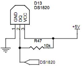
Interface the DS1820 temperature sensor with a microcontroller. The first pin is connected to ground (GND), the third pin to VCC, and the second pin to the microcontroller. When the temperature is sensed, the sensor provides readings to the...
The AN7415 is a monolithic integrated circuit designed for FM stereo demodulation applications. It operates within a voltage range of 1.6 to 7 V DC, making it suitable for handheld FM radios powered by two AA dry cells. This...
The motion games on the Nokia 5800 sparked an interest in creating a real-world version of a racing car controlled by tilting a phone. The motion-controlled robot, named Hercules due to its high torque and speed, is operated via...
Figure A, B, and C illustrate the test rod end clip, with a positive power supply terminating test equipment. The B and C ends are connected in series with the load, where C represents the negative side of the...