
7 Watt Class B Audio Amplifier Circuit

The described amplifier circuit is designed to operate efficiently within the specified power output range, making it suitable for various audio applications. The choice of the NE5534 integrated circuit is crucial as it provides high performance with low noise and distortion levels, which are essential for quality audio amplification. The design philosophy emphasizes simplicity and minimalism, reducing the number of components to enhance reliability and ease of assembly.
The amplifier can deliver a maximum output of 7.5 Watts into an 8 Ohm load, which is adequate for driving small speakers in home audio systems or portable applications. The low Total Harmonic Distortion ensures that the audio output remains faithful to the original signal, making it appealing for audiophiles and casual listeners alike. The internal current limiting feature of the NE5534 protects the circuit from overcurrent conditions, thereby extending the lifespan of the amplifier when driving lower impedance loads.
The direct drive capability from various audio sources simplifies the setup process, allowing users to connect devices without the need for additional amplification stages. The inclusion of an optional preamplifier circuit allows for greater versatility, enabling the amplifier to handle sources with low output levels effectively. The tone control feature provides users with the ability to tailor the audio output to their preferences, enhancing the listening experience.
Overall, this amplifier circuit presents a practical solution for users seeking a compact and efficient audio amplification solution within the specified power range, combining advanced features with straightforward operation.This is a design circuit for amplifier was designed in order to fill the gap in the 3-10 Watts power output range of the audio amplifiers available on RED Free Circuit Designs. Therefore a simple, very low parts-count amplifier, was designed on the same guidelines of the successful 45 Watt Class B Amplifier, but using the excellent NE5534 IC inste
ad of a discrete component op-amp to drive the output "dumper" transistors. This is the figure of the circuit; Due to the maximum operating voltage restrictions of the chip, the output power cannot exceed 7. 5 Watts into 8 Ohm loads, but the Total Harmonic Distortion figures are astonishingly low, much lower than comparable audio amplifiers using a single IC audio amp.
Also due to the internal current limiting of the NE5534, the output power into 4 Ohm loads will be no more than 8 Watts. Other interesting features of this amplifier are the absence of any kind of setup and the possibility to be driven directly by the audio source (CD player, Tuner, iPod etc.
). In any case, a simple, optional preamplifier circuit is provided, allowing to cope with very low output audio sources and featuring a single-knob bass and treble Tone Control. 🔗 External reference
Related Circuits
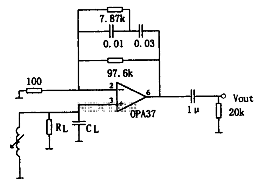
The OPA37 serves as a low-noise preamplifier. The input signal is connected to the inverting input of the OPA37 (pin 3), while the circuit components RL and CL represent the load impedance for electromagnetic pickups. The resistance and capacitance...
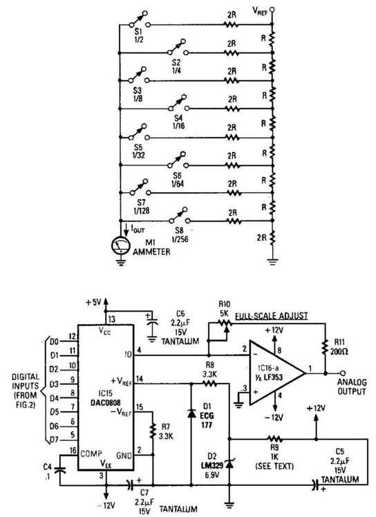
Figure A illustrates an R/2R resistor ladder. Each closed switch increases the current output. A basic channel A/D converter is depicted in Figure B. The voltage reference (D2) is shared among all channels, while the value of the dropping...
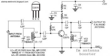
The input coil L1 is composed of four turns of 20 SWG enamelled copper wire, wound slightly spaced over a 5 mm diameter former. It is tapped at the first turn from the ground lead side. Coil L2 is...
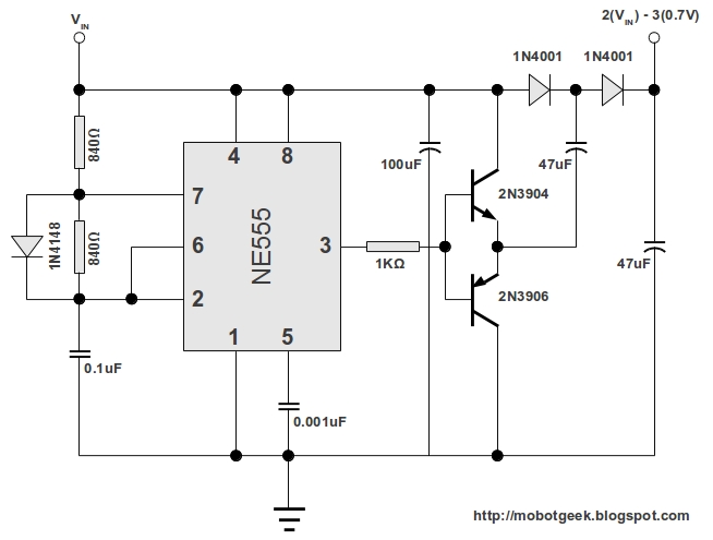
This DC voltage doubler circuit generates a voltage that is double its supply voltage. It is advantageous when a higher voltage level is required from a single lower voltage power supply. Due to the low current consumption in such...
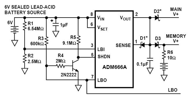
This is a circuit diagram for a solid-state charge detector. It can detect very weak electric fields. The circuit has three components: a 6-volt battery, a light-emitting diode (LED), and a field-effect IC ADM666A. The solid-state charge detector circuit is...
Each part of the LCD has an individual counter, latch, decoder, and driver. The pumping signal is fed back to the motherboard of the LCD. When the display section is disconnected, the phase and amplitude of the motherboard and...