
130kW induction motor synchronization control circuit operation

The described circuit integrates a motor control system that employs several protective and operational relays to ensure safe and efficient motor performance. The use of series resistance in the rotor winding is a common method for controlling the starting current of the motor, allowing for a gradual increase in speed and torque while minimizing the initial inrush current.
The relays KIi through KI3 function as critical components for motor protection. Specifically, these relays monitor the electrical velocity and are designed to disconnect the motor in case of a short circuit or overcurrent situation, thereby preventing potential damage to the motor and associated circuitry. The inclusion of overload protection relays 1KI and 2KI further enhances the safety of the system by ensuring that the motor does not operate beyond its rated capacity, which could lead to overheating and failure.
Voltage relays 1KA to 3KA and the DC relay KAi are essential for maintaining synchronous operation of the motor. These relays monitor the excitation voltage, which is crucial for the motor to function correctly in synchronous mode. If the excitation voltage falls below the required level, these relays can initiate corrective actions to maintain operational stability.
The loss step relay KA2 plays a vital role in the overall functionality of the motor system. In scenarios where the motor experiences a loss of step—often due to mechanical overload or sudden changes in load—it is imperative that the system can recover quickly. The KA2 relay ensures that the motor can return to its synchronous operation state, thereby enhancing the reliability and performance of the system.
Overall, this circuit design reflects a comprehensive approach to motor control, combining protective measures with operational stability to ensure efficient and safe motor operation in various applications. Circuit is shown. Motor using series resistance in the rotor winding start. Drawing, electrical velocity off the relay KIi ~ KI3 for motor short circuit protection; overcurrent relay 1KI, 2KI electrically motive overload protection; voltage relay 1KA ~ 3KA and DC relay KAi ensure synchronous operation must have normal excitation voltage; loss step relay KA2 ensure that the motor in case of losing step into synchronous operation.
Related Circuits
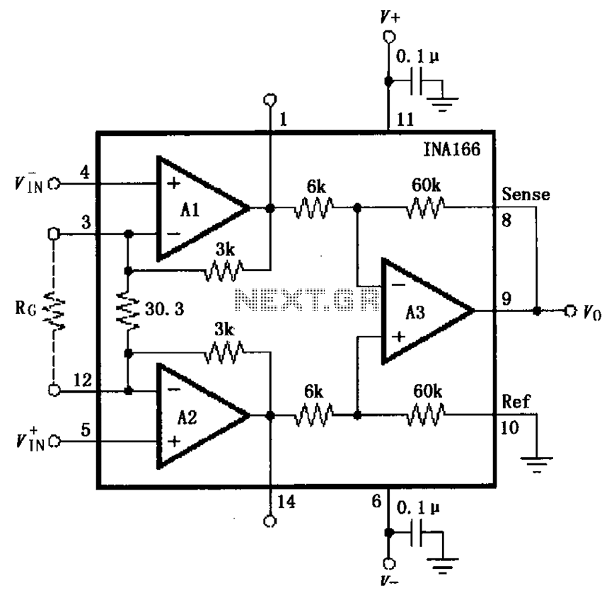
The basic connection circuit for the INA166 includes signal and power connections. A 0.1 µF tantalum capacitor should be used for filtering the chip's power supply terminal, and the PCB layout should be designed to position this capacitor as...

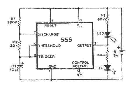
The objective of the circuit is to create an electronic dice using the functionality of a 555 timer integrated circuit operating in astable mode. The electronic dice circuit utilizes a 555 timer configured in astable mode to generate a series...
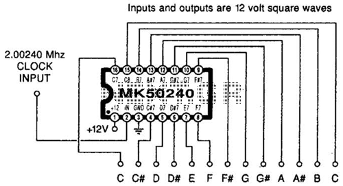
Using an MK50240, this circuit generates 12 top octave tones. The input and output lines can be separated using a binary divider IC to achieve the lower notes. Inputs and outputs are 12-volt square waves. The MK50240 is a specialized...
An integrated circuit is precisely that: an integrated circuit. These small packages combine numerous individual components to perform a specific function. They vary in shape and size depending on their complexity. They are categorized into functions such as audio,...
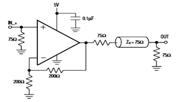
The diagram below illustrates a typical operating circuit for the video line driver using the IC4030/4031 schematic. It incorporates the MAX4030E/MAX4031E, which are unity-gain stable operational amplifiers that offer high-speed performance, rail-to-rail outputs, and 15kV ESD protection, as stated...
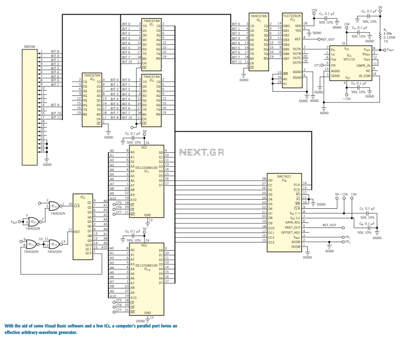
You can use the parallel port of your PC and a few additional components to generate a powerful, easy-to-use arbitrary-waveform generator. By using a Visual Basic program with the circuit in Figure 1, you can generate any waveform (for...