
800W LIGHT DIMMER
The circuit design incorporates a unijunction transistor (UJT) as a triggering device for the TRIAC, which is a semiconductor device used for switching and controlling power. The UJT generates a pulse that is fed into the gate of the TRIAC, allowing it to turn on and off in a controlled manner. The timing of these pulses is influenced by the resistance and capacitance in the circuit, which determines the phase angle at which the TRIAC is triggered.
The pulse transformer serves to isolate the control circuit from the high voltage AC supply, ensuring safety and reducing the risk of electrical interference. The transformer also helps to shape the pulse signal to the appropriate level for triggering the TRIAC effectively.
The circuit is designed to handle a maximum load of 800 watts, making it suitable for various lighting applications. The ability to adjust the conduction angle allows for fine control over the brightness of the lights, providing versatility in lighting scenarios. The dimming range from 0° to 170° enables users to achieve a wide range of illumination levels, from off to nearly full brightness.
In summary, this light dimmer circuit is an effective solution for controlling incandescent lighting, leveraging the properties of unijunction transistors and TRIACs to provide smooth and adjustable dimming capabilities while ensuring safety and reliability in operation.This wide-range light dimmer circuit uses a unijunction transistor and a pulse transformer to provide phase control for the TRIAC. The circuit operates from a 115 volt, 60 Hz source and can control up to 800 watts of power to incandescent tights.
The power to the lights is controlled by varying the conduction angle of the TRIAC from 0° to about 170°. The p.. 🔗 External reference
Related Circuits
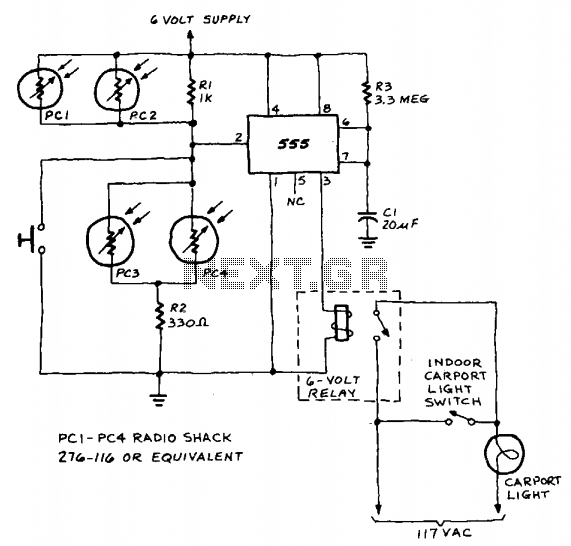
A 555 timer integrated circuit (IC) functions in one-shot mode, triggered by light exposure to photoresistors. These photoresistors typically exhibit a resistance in the range of several megohms, which decreases to several hundred ohms under light conditions, allowing current...
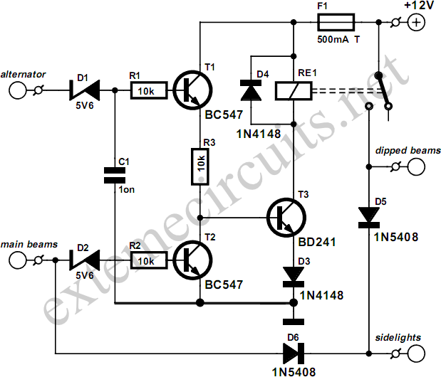
This circuit ensures that the car's lights are automatically activated when the engine is running. It automatically switches on the dipped beams and sidelights, and turns off the dipped beams when the main beams are engaged. The schematic diagram...
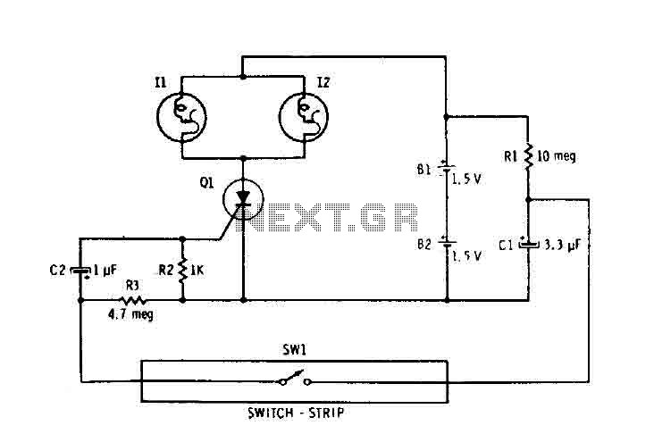
Capacitor C1 is connected continuously through a supply of 3 volts to a 10 megohm resistor R1. The capacitor charges relatively slowly to 3 volts. When switch SW1 is closed, it connects the charged capacitor C1 in series with...
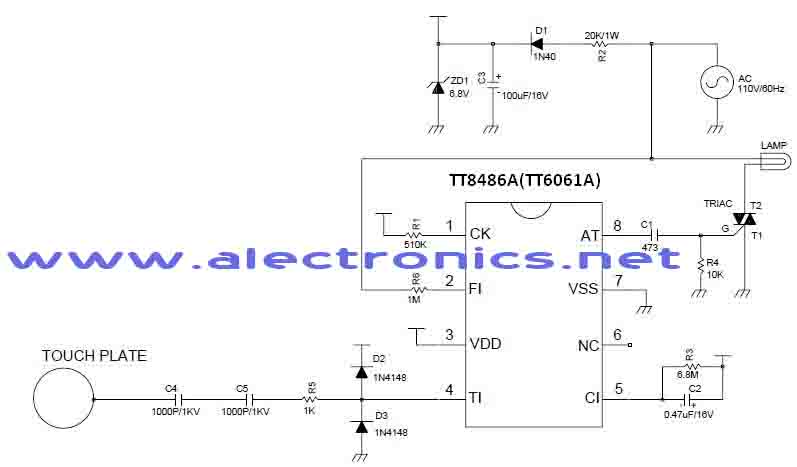
A simple dimmer circuit can be constructed using the CMOS ICs TT8486A and TT6061A, allowing control over the intensity of an incandescent lamp through a touch contact. This electronic touch dimmer can increase the brightness of incandescent lamps in...
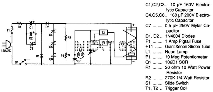
This strobe light operates from standard 120-Vac power. Resistor R1 limits the amount of current applied to the voltage doubler stage, which consists of capacitors C1, C2, C3, and diodes D1, D2, along with capacitors C4, C5, and C6....
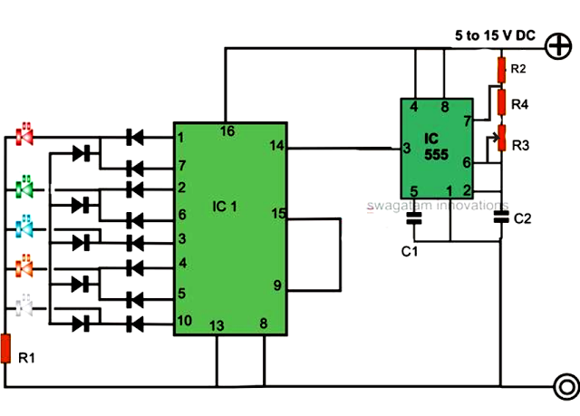
An LED light chaser circuit is an electronic configuration designed to illuminate a group of LEDs in a predetermined sequence. A commonly used integrated circuit (IC) for creating this type of LED sequencer circuit is the 4017. This IC...
Warning: include(partials/cookie-banner.php): Failed to open stream: Permission denied in /var/www/html/nextgr/view-circuit.php on line 713
Warning: include(): Failed opening 'partials/cookie-banner.php' for inclusion (include_path='.:/usr/share/php') in /var/www/html/nextgr/view-circuit.php on line 713