
Lights On!
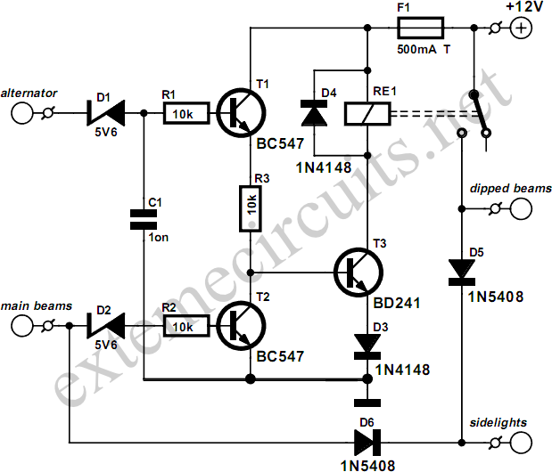
The circuit operates based on a straightforward mechanism that utilizes transistors and a relay to control the vehicle's lighting system effectively. The alternator's output voltage serves as the primary power source, ensuring that the system is active only when the engine is running, thereby preventing battery drain when the vehicle is off. The use of diode D1 for voltage regulation is critical, as it protects the transistors from excessive voltage that could lead to damage.
Transistor T1 acts as a switch that, once activated, allows the current to flow and energizes relay Re1, which in turn activates the dipped beams and sidelights. The design incorporates feedback through the base of T3, ensuring that the relay is only energized when the engine is running and the main beams are not engaged. The interaction between T2 and T3 is crucial for maintaining the desired behavior of the circuit; when the main beams are turned on, T2's conduction reduces the base voltage of T3, leading to the relay's deactivation and ensuring that only the main beams are illuminated.
Diodes D5 and D6 play an essential role in maintaining the sidelights' illumination, regardless of the state of the main beams. This redundancy enhances safety by ensuring that the vehicle is always visible, especially in low-light conditions. Overall, this circuit design is efficient, utilizing common electronic components to achieve a reliable automatic lighting system that enhances vehicle safety and convenience for the driver.This circuit ensures that you will never again forget to switch on the lights of your car. As soon as the engine is running, the dipped beams and the sidelights are automatically switched on. The circuit also causes the dipped beams to be extinguished as soon as the main beams are switched on. As you can see from the schematic diagram, no special components are needed. When the engine is running, the alternator will generate a voltage of more than 14 V. Diode D1 reduces this voltage by 5. 6 V and passes it to the base of T1 via R1. Due to the resulting current, T1 conducts. The amplied current‚ows via R3, the base of T3 and D3 to ground. This causes T3 to also conduct and energize relay Re1. If the driver now switches on the main beams, a current‚ows through D2 and R2 into the base of T2, causing this transistor to conduct. As a result, the voltage on the base of T3 drops, causing T3 to cut off and the relay to drop out. When the main beams are switched off, the previous situation is restored, and the relay again engages.
The dipped beams and the sidelights are switched by the contacts of relay Re1. Diodes D5 and D6 ensure that the sidelights are illuminated if either the dimmed beams or the main beams are switched on. In practice, this means that the sidelights will be on whenever the engine is running, regardless of whether the main beams are switched on.
🔗 External reference
Related Circuits
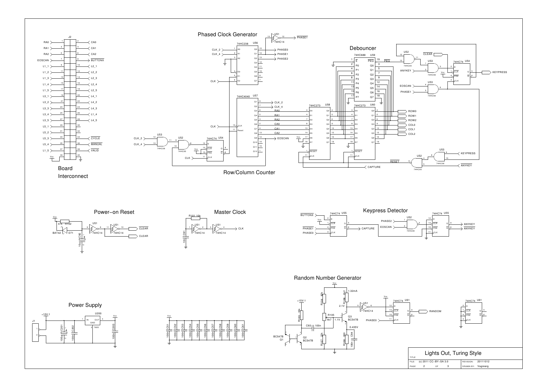
The design is based on the previous analysis of calculating the game in a circular shift register. While designing, it was realized that small extensions to the design would enable additional gameplay features, such as replay and manual input....
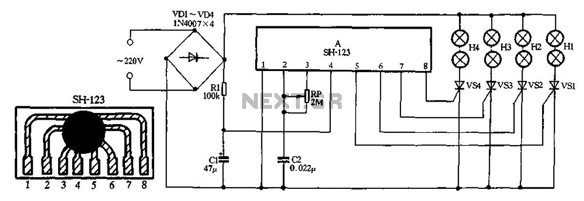
A 220V AC input is processed by a bridge rectifier consisting of diodes VD1 to VD4, which supplies electricity to four lights labeled H1 to H4. The circuit includes a limiting resistor R1 and a filter capacitor C1 to...
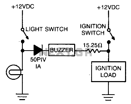
The alarm consists of a diode, buzzer, and a limiting resistor. The diode functions as a switch that enables the buzzer to activate only when the light switch is closed and the ignition is turned off. The circuit described utilizes...
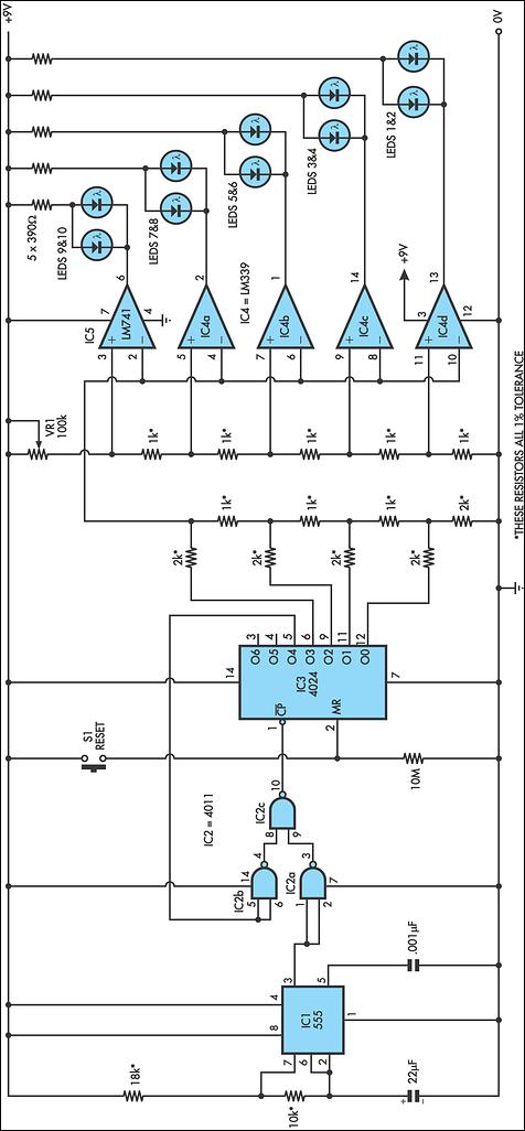
This circuit replicates the starting light sequence used by FISA in Formula One racing. It can be utilized with slot car sets (such as HO scale AFX, Life Like, or Tyco sets) or radio-controlled cars. The circuit employs a...
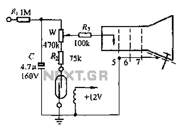
A reed switch is utilized in a TV highlights cancellation circuit. A brightness potentiometer is grounded in series with the reed switch. Under normal operation, the reed contact remains closed, allowing the capacitor C to charge to approximately 160V....

The LED traffic light circuit manages six LEDs (red, yellow, and green) for both north/south and east/west traffic directions. The timing sequence is produced using a CMOS 4017 decade counter in conjunction with a 555 timer. Outputs 1 through...
Warning: include(partials/cookie-banner.php): Failed to open stream: Permission denied in /var/www/html/nextgr/view-circuit.php on line 713
Warning: include(): Failed opening 'partials/cookie-banner.php' for inclusion (include_path='.:/usr/share/php') in /var/www/html/nextgr/view-circuit.php on line 713