
813 SE triode amps
The amplifier operates in a high-voltage environment, necessitating careful attention to safety protocols. The 813 tube, known for its robustness and efficiency in RF applications, is particularly effective when configured in triode mode for audio applications, providing a warm, rich sound characteristic of high-quality audio amplification. The choice of driver tube, the 12HG7, is critical, as it offers superior linearity and lower distortion compared to standard triodes, making it ideal for high-fidelity audio applications.
The microcontroller integrated into the power supply not only manages the sequencing of voltages but also ensures that the amplifier operates within safe parameters. This feature is particularly important in high-voltage designs where component failure can lead to hazardous conditions. The LCD display provides real-time feedback to the user, enhancing the usability of the amplifier while promoting safe operation.
Overall, this single-ended triode amplifier represents a sophisticated design that leverages both classic tube technology and modern electronic control systems, resulting in a powerful and reliable audio amplification solution. The combination of the 813 tube's capabilities with the innovative use of the 12HG7 driver tube exemplifies the potential of tube amplifiers in achieving high-performance audio reproduction.This is a single-ended triode amp that I built using the 813 transmitting pentode, connected as a triode. It`s a fairly powerful SE amp that works very well. It uses a single pentode as the driver (a 12HG7 video amp tube), and a solid-state power supply with a microprocessor controller.
This amp generates around 1000 volts, and the power supply d escribed below can deliver a lot of current. The result is that there is a real hazard from the voltage and energy available. DO NOT TRY AND BUILD ANYTHING LIKE THIS UNLESS YOU ARE COMFORTABLE WITH HIGH VOLTAGES, AND ARE FAMILIAR WITH THE RISKS! Don`t come looking for me if you start a fire or electrocute the cat! When working on high voltages, keep one hand in your pocket, and NEVER LEAVE ANYTHING TURNED ON UNATTENDED!
You`ve been warned. The main peculiarity of the amp circuit, I guess, is the single-tube pentode driver. I experimented quite a bit with the 12HG7 and 12GN7A tubes, both of which are high Gm pentodes designed as video output amplifiers for color TV`s. They are amazing devices, capable of providing very low distortion, high gain, and low output impedance all at the same time.
much better than you can get with any single triode I`ve seen. The driver has a very nice harmonic profile, with the 3rd harmonic always below the 2nd. At lower levels, the 2nd is about the only harmonic that`s measurable. For some reason pentodes seem to have the reputation for creating more high-order harmonics, but it`s simply not true in a single-ended design. This driver tests, and sounds, better than any of the possible two-triode drivers I tried, like 6SN7 direct-coupled, or 6SL7 SRPP.
It also does much better than a 6C45pi-E. I also tried these tubes triode connected with a CCS, and they did well that way - about the same as a 6C45pi did, I guess. But I preferred the pentode connection. Try it, you`ll like it! The output stage is an 813 tube, connected as a triode. The 813 is a ~100W pentode designed for radio transmitter and modulator service, and was used in the WWII timeframe, I think.
It was a common tube in smaller AM broadcast transmitters, especially as a modulator. I got much encouragement, as well as triode curves for the 813, from Paul LeClercq. He has posted info on the 813 triode push-pull amps that he`s built, as well as the triode mode curves for the 813. By the way, the grid lines on the curves are at 10V increments; the first (leftmost) is 0V, the next -10V, then -20V, -30V, etc.
I operate the output stage with a plate voltage of about 850-900V, and a plate current of 100mA. I used fixed bias, which requires around -75V. The OPT is a Tango XE-20S, connected as 5k : 8 ohms. I suspect 5k is probably about the lowest load you`d want to use with the 813. The power supply I built for the 813 amp is a solid-state rectified supply that uses two large toroidal transformers, one for the high voltages, and one for the low voltages (filament power, etc. ) It uses a microcontroller to sequence voltages at power-up, and monitor power supply voltages and plate current, as well as temperature.
Data is displayed on an LCD display, and if any parameter goes out of tolerance the amp is shut down and an error message is displayed. The HV supply uses Plitron 067053201 225VA toroidal transformer, which has two 175V windings that are connected in series to get 350 VAC.
A voltage doubler is used, which produces around 1000 volts, and at the midpoint of the doubler capacitors, about 500V. These voltages are filtered with RC filters to get the 813 B+ of about 850-900V and the driver B+ of around 400V.
The driver G2 supply of 150V is derived from the 400V supply with a zener regulator. My original HV supply design was to use linear regulation. I never got the regulators to work to my satisfaction, and after blowing up a handful of power FET`s, gave it up in favor of a simple RC filter. Chokes would be better than resistors, but at this po 🔗 External reference
Related Circuits

This simple circuit can be used to flash incandescent lamps with a power rating of up to 10W. The circuit is ideal for creating flashing beacons on automobiles and similar applications. It consists of an astable multivibrator based on...
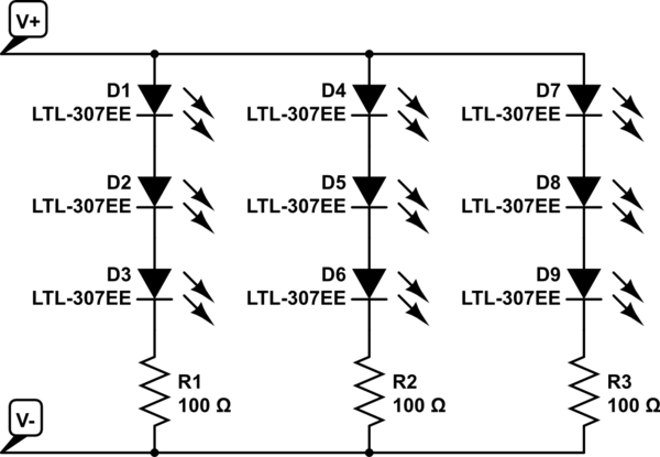
The project involves installing LED strips in a car's tail lamps to replace conventional bulbs. The required lengths for the LED strips are 16 inches, 15 inches, and 14 inches to fit properly within the housings. The selected LED...
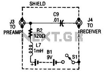
The purpose of the receiver/interface circuit is to pass RF to the receiver through capacitor C9, while adding DC power to the feedline through resistor R2 and RF choke L7. The receiver/interface circuit is designed to facilitate the transmission of...
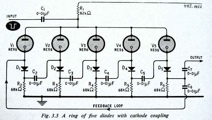
The above shows a home-built digital clock that utilizes Nixie tubes for display. Unlike most contemporary Nixie clocks, this design does not employ transistors or integrated circuits for driving the tubes. Instead, the driving logic is constructed using neon...
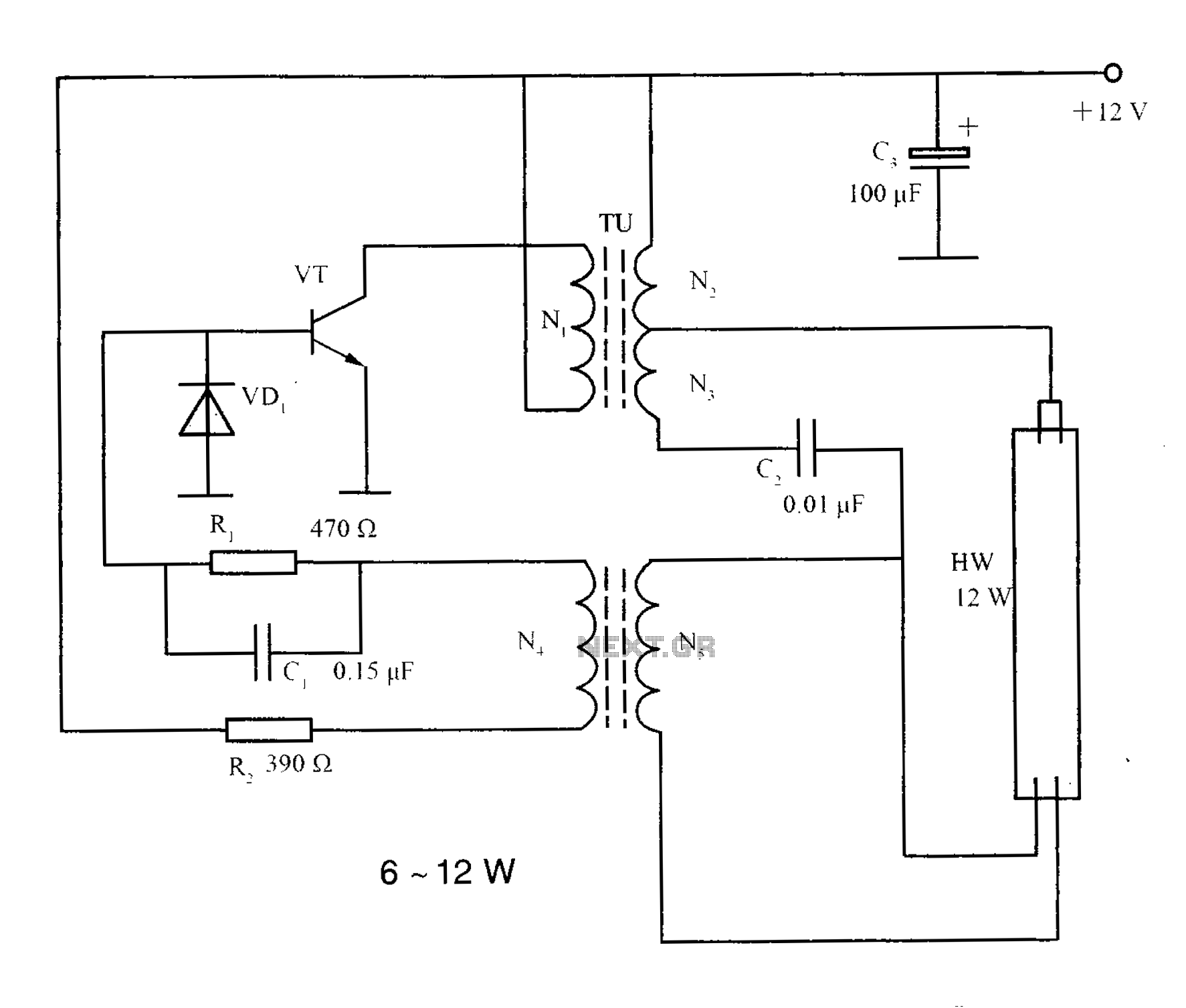
The lighting inverter circuit is designed for 6 to 12W fluorescent lamps. It operates by first bucking the mains voltage, followed by rectification and filtering to charge a battery. When the inverter is activated, it generates a high-frequency alternating...
A collection of guitar fuzz, preamp, and operational amplifier (op-amp) electronic circuits and schematics designed for various guitar effects and distortion effects. This compilation includes a diverse range of electronic circuits that cater to guitarists seeking to enhance their sound...
Warning: include(partials/cookie-banner.php): Failed to open stream: Permission denied in /var/www/html/nextgr/view-circuit.php on line 713
Warning: include(): Failed opening 'partials/cookie-banner.php' for inclusion (include_path='.:/usr/share/php') in /var/www/html/nextgr/view-circuit.php on line 713