
in making incandescent lamps

The circuit is designed around a basic astable multivibrator configuration, which generates a continuous square wave output. The transistors Q1 and Q2 are configured in a feedback loop, allowing them to alternately switch on and off, thus creating the flashing effect. The timing capacitor C1, in conjunction with resistors connected to the base of the transistors, sets the frequency of the oscillation. The value of C1, along with the resistors, can be adjusted to change the flashing rate according to the application requirements.
The inclusion of switch S1 allows for manual control of the circuit, providing the ability to turn the flashing effect on or off as needed. This feature is particularly useful in automotive applications where the flashing beacon may only be required in specific scenarios.
For applications involving fluorescent or tube lamps, it is crucial to ensure that the circuit can generate sufficient voltage to ionize the gas within the lamp. This typically involves a step-up transformer or a similar high-voltage circuit design that can provide the necessary ionization energy. The efficiency of fluorescent lamps makes them an excellent choice for battery-operated systems, as they consume less power compared to incandescent lamps while providing adequate illumination.
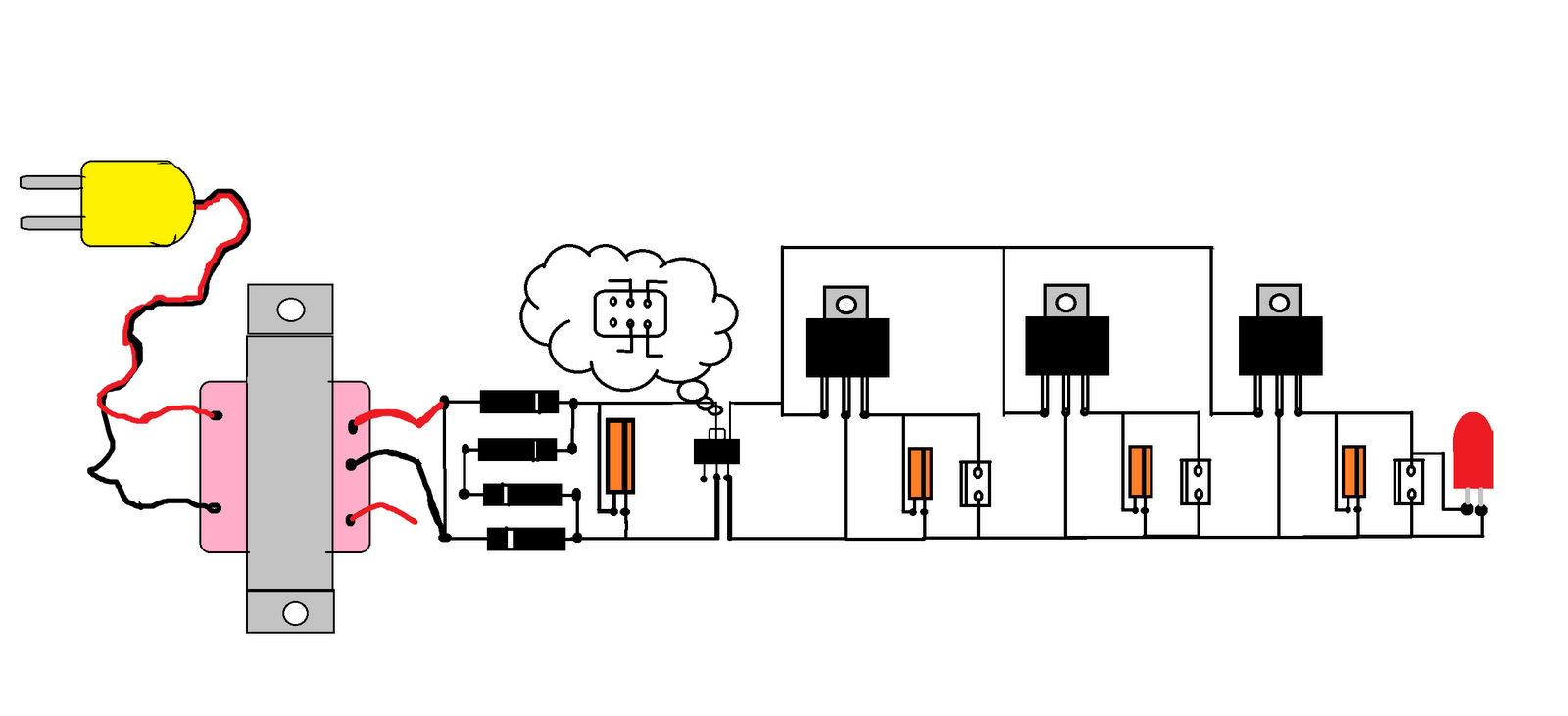
In summary, this circuit serves as a versatile solution for creating flashing light effects, suitable for various applications, particularly in automotive and portable lighting contexts. The design's simplicity and efficiency make it a practical choice for engineers and hobbyists alike.This simple circuit that can be used to flash incandescent lamps up to 10W power rating. The circuit is ideal for making flashing beacons on automobiles and other applications like that. The circuit is nothing but an astable multi vibrator based on Q1&Q2 ( BC557&BD139). The capacitor C1 is the main timing element which determines the flashing rate o f the circuit. The switch S1 can be used as an ON/OFF switch. Fluorescent lamp or tube lamp (TL) has good efficiency. This high efficiency feature make it suitable for battery operated lighting application. To drive the tube lamp, we need high voltage to make the gas inside the tube get ionized. 🔗 External reference
Related Circuits
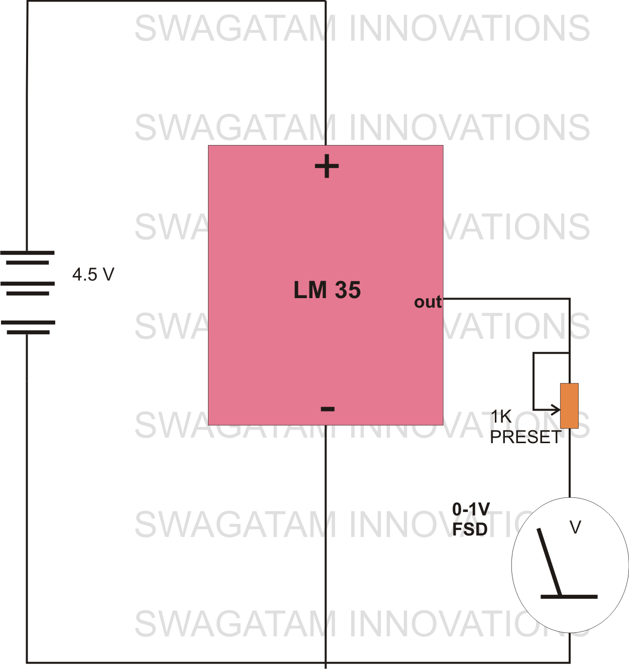
The circuit diagram provided illustrates a straightforward setup. There is no requirement for complex circuitry; simply connect a 0-1 V full-scale deflection (FSD) moving coil meter across the designated pins of the integrated circuit (IC). Adjust the potentiometer as...

This article is authored by Yash Tambi, a Core Committee Member of roboVITics. It discusses RF-controlled robots, which are among the simplest types of robots. The essential components include a few readily available integrated circuits (ICs), a 433 MHz...
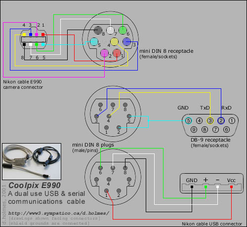
Instructions for creating a combined dual serial and USB cable for the Nikon Coolpix 990 (e990) camera. To construct a combined dual serial and USB cable for the Nikon Coolpix 990 (e990) camera, it is essential to understand the pinout...
Very simple, versatile modular design. The purpose of this circuit was to create a ring in which LEDs or Lamps illuminate sequentially. Its main feature is a high versatility: you can build a loop containing any number of LEDs...

Using a modern multimeter to measure current can sometimes be difficult. Many of these meters will only measure up to one amp. However, many 112-volt DC powered projects draw a lot more than that. If you have ever thought...
This document explains how to create a wireless car using integrated circuits (ICs) and requires additional components such as registers. It is recommended to visit an electronics shop to purchase a wireless car kit operating at 413 MHz ASK...