
A control circuit automatic irrigation
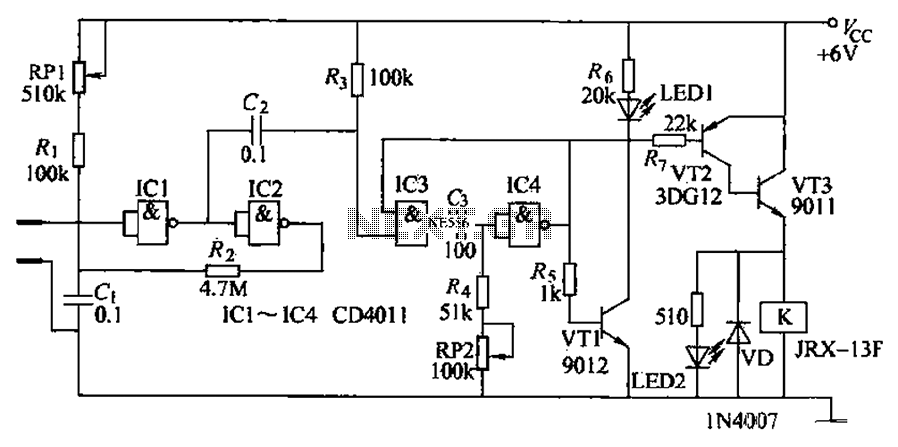
The operation of the circuit begins with the soil moisture sensor detecting the moisture level. When the moisture is adequate, the resistance between the two sensor probes remains low, resulting in a low input voltage to the Schmitt trigger. Consequently, the Schmitt trigger does not activate, keeping IC4's output high, which prevents the relay from engaging. As a result, the pump motor (M) remains off, and LED2 does not illuminate, while LED1 lights up to indicate sufficient soil moisture.
When the soil becomes dry beyond a specific threshold, the resistance between the probes increases, triggering the Schmitt trigger. This action generates a negative pulse at the output of the monostable multivibrator (IC4), which turns off VT3 and extinguishes LED1. Simultaneously, VT1 and VT2 conduct, energizing the relay (K) and activating the pump motor. LED2 lights up, signaling that the irrigation system is operational.
Resistor R1 is adjustable to set the soil moisture threshold for irrigation initiation, while the resistance of potentiometer RP2 can be modified to control the duration of the irrigation cycle. This flexibility allows for tailored irrigation schedules based on specific crop requirements and environmental conditions, ultimately optimizing water usage and enhancing agricultural productivity. The schematic design effectively integrates these components to create a reliable and efficient automatic irrigation system. Automatic irrigation control circuit can automatically crop irrigation according to the size of soil moisture. It can be widely used in state farms, orchards, Schomburg materia ls vegetable greenhouses, greenhouse cultivation and sprinkler vast farmland. (1) circuit automatic irrigation controller circuit consists of soil moisture sensor, Schmitt trigger, monostable, LED was shown circuit and control the implementation of circuit, as shown in Figure 8-2. Schmitt trigger consists of four NAND gate integrated circuit 1C1-1C2 and resistor Ri, Rz, capacitors Cl, c2, potentiometer RP1 composition.
One-shot by IC3 ~ lC4, wind resistance, R4, potentiometers RP2 and capacitance G components. LED display circuit consists of transistors VT3, light-emitting diodes LED1, LED2 and resistor Rs ~ R7 composition. Control the implementation of circuit by the resistors Ra, transistor VTI,, relay K and diode. f) components., (2) the circuit works at a suitable soil moisture, humidity sensor electrically Phoenix value between the two smaller probes, input ici showed a low potential, Schmitt trigger can not be triggered.
At this point IC4 output high, the VT1 and VT2 end. K does not pull station, pump motor M does not work t LED2 does not emit light; while VT3 conduction, LED1 is lit, the suitable soil moisture. When the soil is dry to a certain extent. Humidity sensor resistance value between the two probes rises to a predetermined value, the Schmitt trigger triggered while flipping through G provide a negative jump pulse single-shot, the single-shot flip, IC4 output low, so VT3 deadline, LED1 off; VT1 and VT2 conduction, K pull, the pump power work, start irrigation, while LED2 lit; indicates pump electric motive normal operation.
R1 is used to control soil moisture, adjust the resistance can be determined according to the timing of irrigation J soil moisture. Adjust the resistance of RP2, can irrigate the length of time to adjust.
Related Circuits
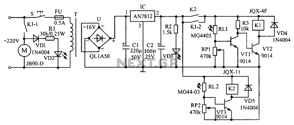
Commonly used in industrial and mining enterprises, a power mixer is employed for mixing materials. Due to the presence of odors or dust, operators should maintain a safe distance from the equipment. The system utilizes light control for operation....
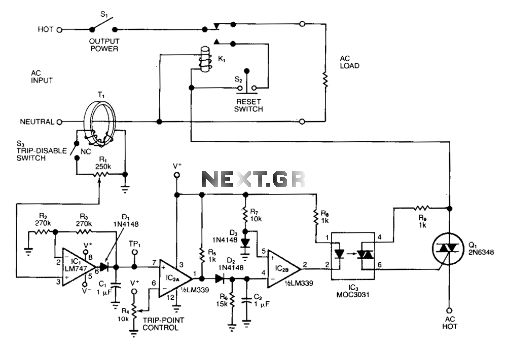
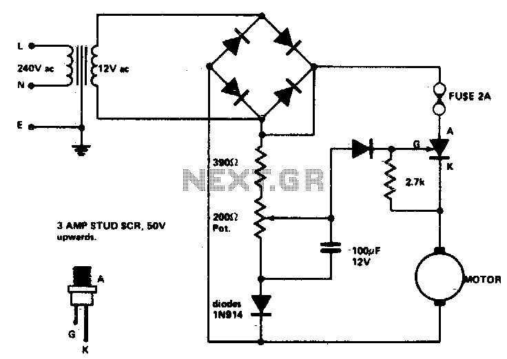
The adjustable circuit breaker responds in 0.02 seconds under all conditions, provided a fast relay is selected for K1. For moderate overload conditions, it is preferable to use a fuse or a fast-acting breaker. The toroidal transformer T1 senses...
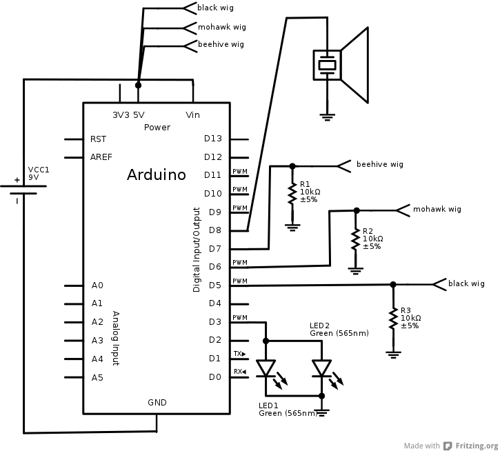
The interaction design for the singing pig was to have a different song start playing when a different wig is placed on the pig. The pig needed to stand by itself without being connected to anything else, and the...
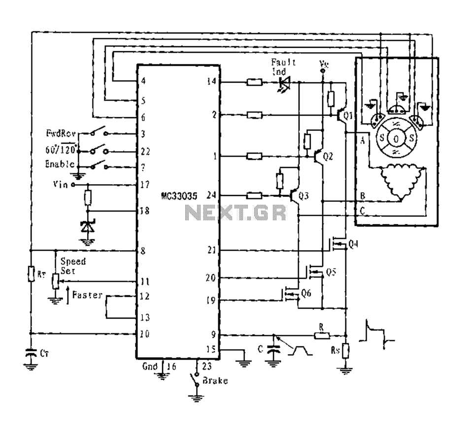
The application circuit is a three-phase full-wave six-step driving circuit for an open-loop motor controller. It features a power switching transistor of the Darlington type, specifically PNP, while the lower power switching transistors are N-channel power MOSFETs. Each device...
Low voltage speed control provides excellent starting torque and effective speed regulation. Additionally, a reversing switch can be integrated into the motor leads. Low voltage speed control circuits are essential in applications where precise motor control is required, such as...
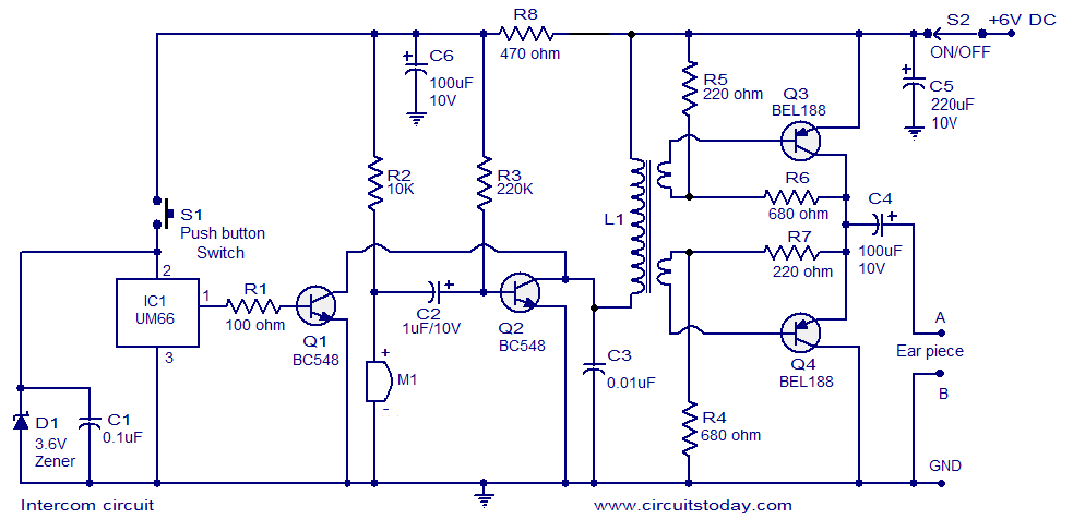
A straightforward intercom circuit designed using transistors. It does not require a changeover switch and can be used similarly to a telephone. This intercom circuit utilizes transistors to facilitate communication between two or more stations without the need for complex...