
A decorative quartz voice packet clock circuit

The circuit described involves a combination of amplifiers, monostable and astable multivibrator configurations, and LED control for visual output. The directly coupled amplifier formed by BGl and BG2 is responsible for signal amplification, ensuring that the subsequent stages receive a sufficient signal for processing. The monostable trigger circuit, composed of BG and BG4, is crucial for generating a stable output pulse in response to an input trigger, which could be an audio signal detected by the sound detection element or a quartz timekeeping signal.
The alternating red and green flashing of LED13 is indicative of the multivibrator configuration created by BGg and BGlo, which oscillates between two states, driven by the high potential from BG4. The inclusion of the sound detection element enhances the circuit's interactivity, allowing it to respond to external stimuli such as claps, thereby creating a dynamic visual display.
The capacitor group connected to BG4 plays a pivotal role in determining the timing characteristics of the monostable circuit. The charge and discharge cycles of the electrolytic capacitor C5 dictate the duration of the stable state before the circuit returns to its original state, thus controlling the flashing of the LEDs.
The astable circuit formed by BG5 and BG6, along with the arc tube LEDi-I2, contributes to the overall functionality of the circuit by providing a continuous oscillation that can be visually represented through the LED groups. The division of LEDi into three groups allows for a more complex light pattern, adding to the aesthetic appeal of the circuit while maintaining synchronization with the input signals.
In summary, this circuit integrates various electronic components to create a responsive, visually engaging display that reacts to sound and timekeeping signals, utilizing amplifiers, monostable and astable configurations, and LED indicators to achieve its intended functionality. BGl, BG2 composition directly coupled amplifier, BG, BG4 is composed of monostable trigger circuit, without receiving prior to the trigger signal, BG3 saturated conduction, BG4 off, this time for a steady state, BG4 collector was high potential, resulting in BGu saturated conduction, so that BGg, BGlo composed multivibrator work, color tube LED13 alternately flash red and green, the Central Plains as the Y-clocks speaker sound detector element, which receives quartz timekeeping signal itself or external audio signal clap after the transformer impedance transformation by the B to BG. Base into line amplification, the amplified signal is triggered via the capacitor group BG4 island pole monostable flip is temporarily stable state, that is, BG, closing, BG4 conduction, this time BG3 collector was high potential, BGa conduction so BG5, BG6, Bq astable circuit thereof.
12 of the arc tube LEDi-I2 into D, E, F three groups were connected BGs a collector B on the island, LEDi one: luminous cycle, after a period of delay, the potential of the electrolytic capacitor c5 increased so Bq conduction, monostable flip back to normal steady-state, BG. Off, LED, ~.. Off, BGn conduction, continue to flash red and green color tube, if we clap or punctual timekeeping, and repeat the process.
Related Circuits
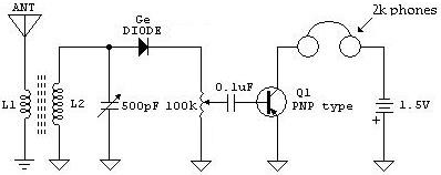
The following schematic illustrates a Crystal Radio Receiver Circuit Diagram that incorporates audio frequency (AF) amplification utilizing a Germanium transistor. The inclusion of AF amplification enhances the audio output quality. The Crystal Radio Receiver Circuit is a simple yet effective...
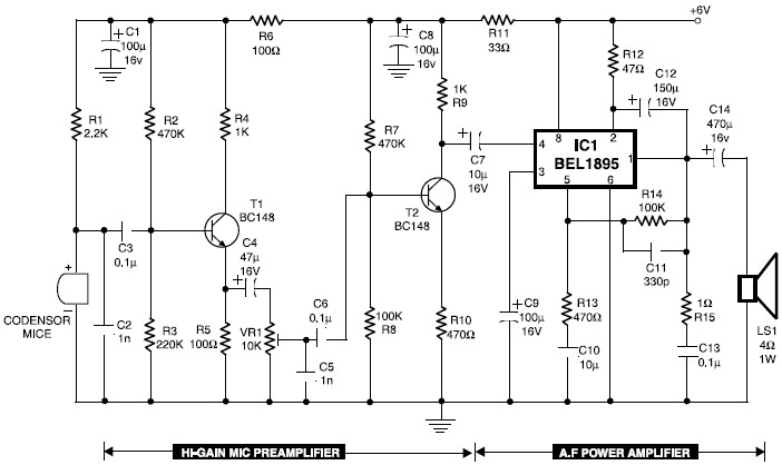
Transistors T1 and T2 form the microphone preamplifier. Resistor R1 provides the necessary bias for the microphone condenser, while preset VR1 functions as a gain control to adjust the gain level. To enhance audio power, the low-level audio output...
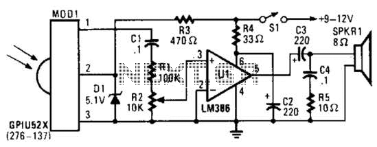
This circuit utilizes an infrared pulse-to-audio converter to assist in troubleshooting infrared remote controls, making it an effective tool for detecting infrared light sources. It employs a photo cell module (Radio Shack P/N 276-137) to detect IR radiation and...
Instructions for creating a Clap-Clap On/Clap-Clap Off switch circuit. This guide provides the necessary information for constructing a clap-activated switch. The Clap-Clap switch circuit is an innovative design that utilizes sound activation to control electronic devices. The primary components of...
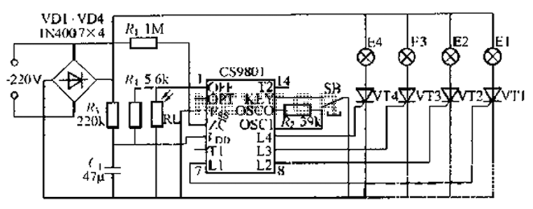
The ASIC is a flashing light string controller featuring four outputs. It includes a single key cycle control with six different lighting effects, and it allows for the selection of either 16 or 8 patterns. The circuit incorporates a...
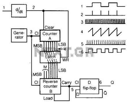
An input rectangular signal is differentiated to produce short impulses from its edges. These impulses transfer the content of counter A to a latch that clears the counter after a very brief period. Counter A counts impulses at a...