
a regularly repeating interval timer

The adjustable output timer circuit typically employs a combination of a timer IC, such as the 555 timer, and various passive components like resistors and capacitors to define the timing characteristics. The configuration can be set in either monostable or astable mode, depending on the desired operation.
In the monostable mode, the circuit generates a single output pulse when triggered, with the width of the pulse determined by the resistor-capacitor (RC) time constant. The output period can be adjusted by changing the values of the resistor and capacitor. For longer durations, larger capacitance values and higher resistance values are used.
In the astable mode, the circuit continuously oscillates between high and low states, producing a square wave output. The frequency of oscillation and duty cycle can be adjusted by modifying the resistors and capacitors in the feedback loop. This mode is useful for applications requiring regular intervals of output without the need for a trigger signal.
To enhance functionality, additional components such as diodes may be included to prevent reverse polarity or to shape the output signal. Furthermore, integrating a microcontroller can provide more sophisticated timing control and programmability, allowing for complex timing sequences and user interfaces.
Overall, this adjustable output timer circuit is versatile and can be adapted for various applications, including automation systems, time delay relays, and periodic signal generation. Proper selection of components and configuration is crucial to meet the specific timing requirements of the intended application.This circuit has an adjustable output timer that will re-trigger at regular intervals. The output period can be anything from a fraction of a second to half-an-hour or more - and it can be made to recur at regular intervals of anything from seconds to days and beyond.. 🔗 External reference
Related Circuits
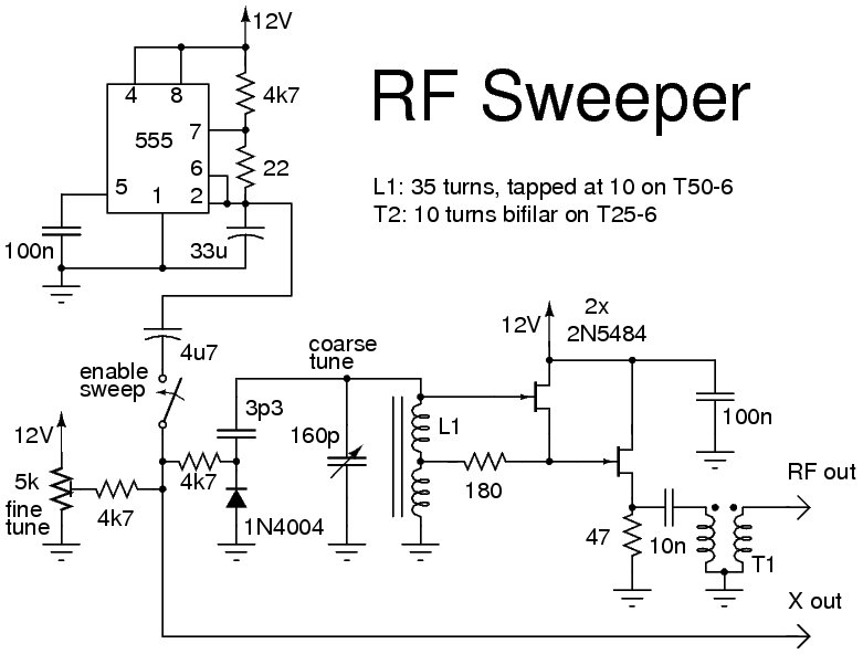
The following circuit illustrates the use of a 555 Timer IC for an RF sweeper application. Features include the utilization of a 1N4004 diode and a JF1OZL, which employs a potentiometer for precise frequency control. The circuit utilizes the 555...
A simple astable timer is constructed using a 555 timer IC. The mark (on) and space (off) durations can be set independently. The timing circuit comprises resistors Ra, Rb, and capacitor Ct. The capacitor Ct charges through resistor Ra,...
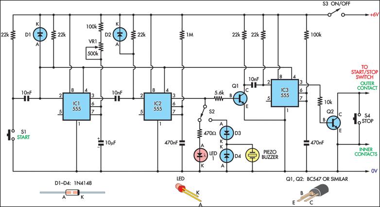
Integrate an inexpensive stopwatch into this circuit to create an accurate reaction timer. The circuit is connected in parallel with the start/stop button of the watch through a 2.5mm socket, which fits securely in one corner of the casing....
Anyone who has designed circuits using the 555 timer chip has, at some point, wished for the ability to program longer timing periods. Timing intervals exceeding a few minutes are challenging to achieve due to the significant impact of...
A 100 second delayed turn ON relay RL1 switch, if plug power +12V in circuit. In Fig.2 see a two range 6-60 second and 1-10 minute auto turn off relay timer circuit, with 555. Part List R1=1 Mohms C4=100nF...

The circuit can be arranged in a circular format to represent the 12 hours of a clock face, with an additional 12 LEDs positioned in an outer circle to indicate 5-minute intervals within each hour. Four extra LEDs are...