
555 Timer IC For RF Sweeper

The circuit utilizes the 555 Timer IC, configured in astable mode, to generate a continuous square wave output. This output can be adjusted to sweep through a range of frequencies, making it suitable for RF applications such as signal scanning or interference testing. The 1N4004 diode serves as a protective component, preventing reverse voltage spikes that could damage the timer IC or other components in the circuit.
The JF1OZL, a specific type of RF oscillator, is integrated into the design to enhance the frequency tuning capabilities. A potentiometer is included in the circuit, allowing for fine adjustments to the frequency output. This feature is particularly useful in RF applications where precise frequency control is essential for effective operation.
The overall design emphasizes stability and reliability, with the 555 Timer providing a robust solution for generating the desired RF signals. The combination of the timer IC, diode, and potentiometer creates a versatile circuit capable of meeting various RF sweeping requirements. Proper layout and component selection will ensure optimal performance and longevity of the circuit in practical applications.The following circuit shows about 555 Timer IC For RF Sweeper. Features: used a 1N4004 Diode, JF1OZL uses a pot for a fine frequency control .. 🔗 External reference
Related Circuits
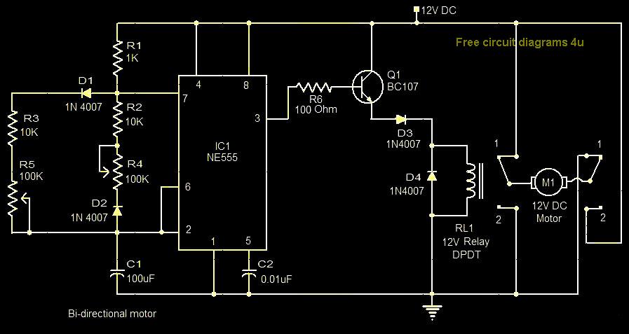
This circuit illustrates a bi-directional motor control circuit utilizing the NE555 integrated circuit (IC). Features include a 12V DC power supply, with the IC employed to control relay RL1. The bi-directional motor control circuit designed with the NE555 IC allows...
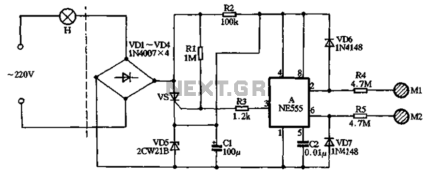
The circuit illustrated in the figure features a dashed line on the left, representing a standard lighting circuit, while the right side is responsible for the dual functionality of touch activation using the NE555 timer. Components VD1 through VD4...
This schematic diagram illustrates a 555 IC water level sensor and detector alarm circuit. The circuit is powered by the emitter current of the BC109C transistor. The 555 timer operates as an astable oscillator in this configuration. Under dry...
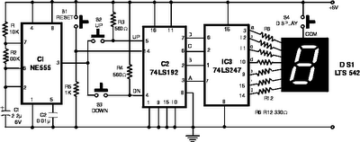
The following circuit illustrates the NE555 Timer used in an electronic scoring game circuit diagram. Features: The circuit consists of a timer integrated circuit (IC), along with various additional components. The NE555 timer is a versatile and widely used integrated...

The following circuit illustrates a basic monostable multivibrator, which is based on the 555 Timer IC. Key features include pin 4 functioning as the RESET pin, with the time period defined by the equation t = R1 x C1. The...
The following circuit illustrates a curtain control circuit diagram. This circuit is based on the 555 integrated circuit (IC). Features include a switch for manual control, the IC, and additional components. The curtain control circuit utilizes the 555 timer IC...