
Speed-Control for Small Asynchronous Induction Motor

The schematic for controlling the speed of a low-power induction motor typically incorporates several key components that work together to adjust the motor's operational speed effectively. The primary method of speed control in such motors involves varying the voltage or frequency supplied to the motor.
One common approach is the use of a variable resistor or potentiometer connected to a triac or a solid-state relay. The variable resistor allows the user to adjust the resistance in the circuit, which in turn alters the voltage reaching the motor. This change in voltage results in a corresponding change in the speed of the motor.
In more sophisticated designs, a pulse-width modulation (PWM) controller may be employed. This method involves switching the motor's power supply on and off at a high frequency, effectively controlling the average voltage and current supplied to the motor. The duty cycle of the PWM signal can be adjusted to vary the speed of the motor, providing a smooth and efficient operation.
Additionally, the circuit may include protective components such as fuses or circuit breakers to prevent damage due to overload conditions. Capacitors may also be present to filter out electrical noise and ensure stable operation.
The schematic will typically include a power supply section that provides the necessary voltage to the motor, a control interface for user input, and a motor driver section that translates the control signals into motor operation. The integration of these components allows for effective speed control of low-power induction motors used in various applications, including household fans.On the circuit diagram below show us a schematic which is used to set the speed of a low-power induction motor, such as those which can be found in fan.. 🔗 External reference
Related Circuits
This involves controlling servo motors through software programming using the PIC 16C71 microcontroller. The input signals range from 0 to 5V. The circuit for controlling servo motors with a PIC 16C71 microcontroller is designed to provide precise control over the...
The circuit is designed to operate with an external power supply, which is why it does not include a transformer, rectifier, or filter capacitors in the schematic. However, these components can be added if desired. To utilize the circuit,...
The circuit features four pins labeled "Controller pin 1," "Controller pin 2," "Controller pin 3," and "Controller pin 4," which are responsible for controlling the motion and direction of the stepper motor based on the step sequence programmed into...
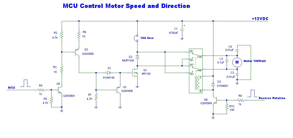
This is a power motor controller circuit designed for 12V applications. It utilizes a microcontroller unit (MCU) for signal control, operating at a high voltage level of approximately 3V. The circuit allows for the motor to be controlled to...
This page shows some methods of track routing control for Stall-Motor type switch machines. The principle method uses a 2 Pole - Multi Position rotary switch while an alternate uses optoisolators and transistors to select the routes. The last...
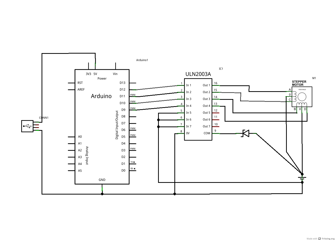
The ULN2003A and Zener diode are components from the driver board within the same device. The motor in question has five wires, while the schematic depicts a six-wire motor. It is assumed that the difference lies in the fact...