
Stereo FM Transmitter Using BA1404

The BA1404 FM stereo modulator is designed for efficient transmission of audio signals in the FM band. The integrated circuit features a stereo modulator that allows for the encoding of audio signals into a stereo format, which is essential for high-quality sound reproduction. The FM modulator section converts the audio signals into frequency-modulated signals suitable for broadcast.
The RF amplifier circuitry within the BA1404 enhances the output signal strength, ensuring that the transmitted signal can cover a wider area and maintain clarity. The operating frequency range of 76 to 108 MHz makes this circuit suitable for various applications, including personal FM transmitters, wireless audio systems, and other short-range communication devices.
Power supply requirements for the BA1404 are flexible, accommodating a voltage range of 1.25 to 3 volts. This allows for the use of various power sources, including batteries and low-voltage power supplies, making the circuit versatile for portable applications. Proper bypass capacitors should be included in the design to stabilize the power supply and minimize noise, which is critical for maintaining signal integrity.
In summary, the BA1404 circuit presents a compact and efficient solution for FM audio transmission, integrating essential components into a single package, thereby simplifying design efforts while providing reliable performance.The circuit is based on the IC BA1404 from ROHM Semiconductors. BA1404 is a monolithic FM stereo modulator that has built in stereo modulator, FM modulator, RF amplifier circuitry. BA1404 FM transmitter can be operated from 76 to 108MHz and power supply for the circuit can be anything between 1.25 to 3 volts.
. 🔗 External reference
Related Circuits
This is a battery charger circuit that has the advantage of automatically disconnecting the battery when charging is complete. The voltage sensor used in this circuit is the LM301 IC, which serves to disconnect the battery when the charging...
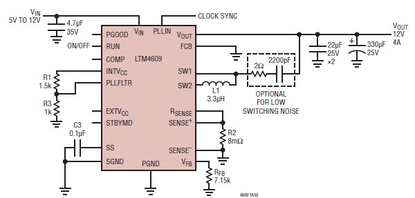
A very simple, high-efficiency switching mode buck-boost power supply circuit can be designed using the LTM4609 switching regulator IC. This circuit will provide a fixed output voltage of 12 volts. As illustrated in the schematic, the switching power supply...
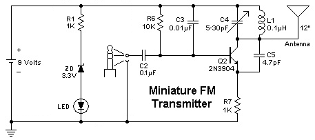
To replace a microphone with a 3.5" audio jack in a circuit, modifications will be necessary. The circuit currently utilizes an electret microphone, and adjustments must be made to accommodate the audio jack for audio transmission. The audio jack...
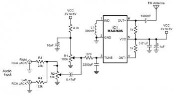
The FM transmitter circuit is built using a single MAX2606 chip. This simple FM transmitter connects a home entertainment system to a portable radio, allowing music to be played in one room and listened to in another, such as...

This circuit diagram indicates when the input voltage deviates from two defined limits, V1 and V2. The limits are adjustable, and the circuit is designed to trigger the adjustable window. The supply voltage, Vcc, must be at least 2...

This design circuit is a tone control circuit that utilizes the popular Baxandall configuration, a straightforward circuit layout that allows for continuous boost and cut control. The circuit is inexpensive to construct and is frequently implemented in commercial products....