
AC/DC Microammeter Circuit

The circuit in question is designed to provide precise measurements of very low DC currents, often in the microampere range. It typically incorporates an operational amplifier (op-amp) to amplify the small signals received from the current sensing element. The circuit may include a shunt resistor placed in series with the load to develop a measurable voltage drop proportional to the current flowing through it.
The output from the op-amp is fed to an analog meter, which is calibrated to display the current reading accurately. The choice of an analog meter allows for a visual representation of the current flow, making it easier to observe fluctuations in real-time.
The design may also feature additional components such as resistors for gain setting, capacitors for filtering noise, and possibly diodes for protection against reverse polarity. The power supply for the circuit should be stable and capable of providing the necessary voltage levels to ensure accurate readings.
Overall, this micro ampere meter circuit is suitable for applications in laboratories, electronics testing, and other scenarios where precise low-current measurements are required. Proper calibration and component selection are crucial to achieving optimal performance and accuracy in the readings.This is a take-off on Mr. Marian s ""Simple Micro Ampere Meter Circuit"" that utilizes active circuitry and an analog meter to make sensitive DC current meas.. 🔗 External reference
Related Circuits
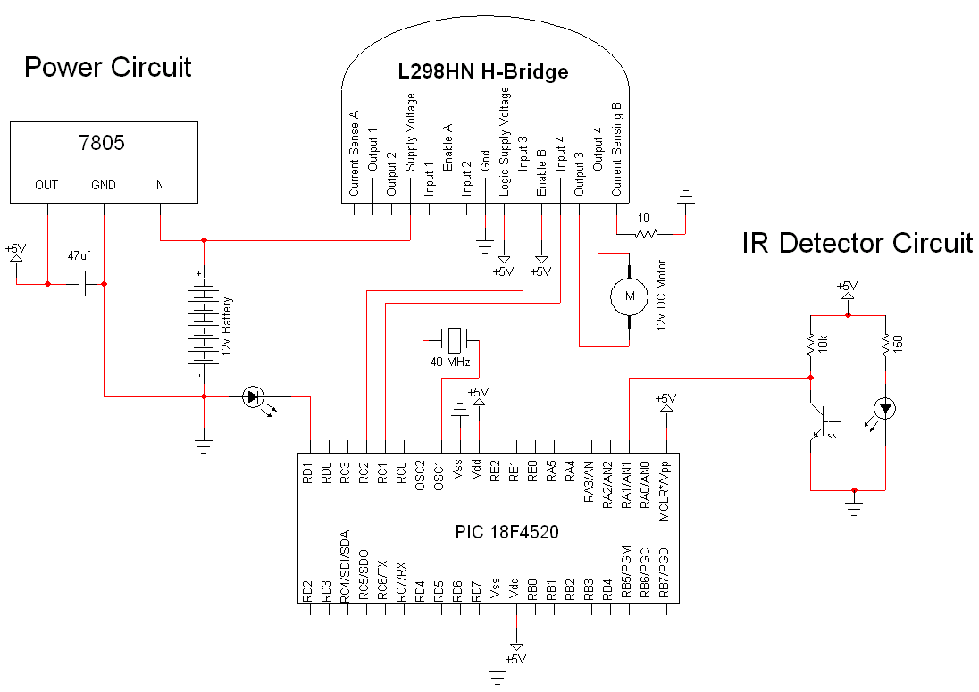
The simple motor optical encoder circuit is not particularly difficult; however, it requires careful verification to ensure all connections are correct before initial operation. The primary components utilized in the circuit include the 7805 voltage regulator, the PIC18F4520 microcontroller,...
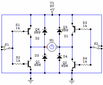
You have 4 transistors, wired as ON OFF switches. Two signal lines allow you to run the motor in one direction, when reversed, the motor runs in the other direction. It's very straightforward to use and build, but be...
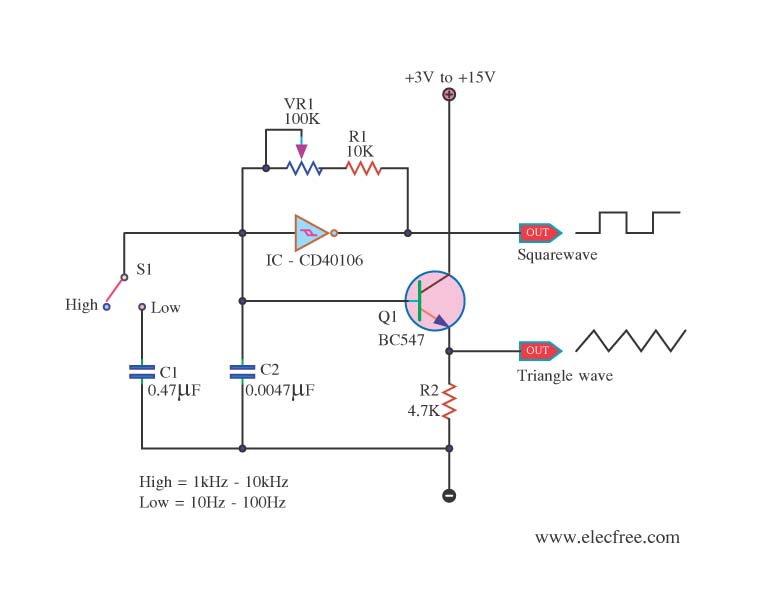
This is a function generator project that can be used as a triangle and square wave generator. The main components include the CD40106, a popular CMOS integrated circuit, and a standard transistor. The function generator circuit utilizes the CD40106, which...
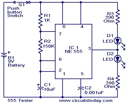
This schematic requires clarification. It is assumed that pin 2 is connected by a wire to pin 6, although this connection appears to be unclear. The circuit in question involves a schematic where pin 2 and pin 6 are interconnected....
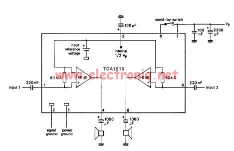
The TDA1519 circuit can deliver 2x6 watts of output power. The TDA1519 is an integrated class-B dual output amplifier housed in a 9-lead single in-line (SIL) plastic medium power package, primarily developed for car radio applications. The TDA1519 amplifier is...
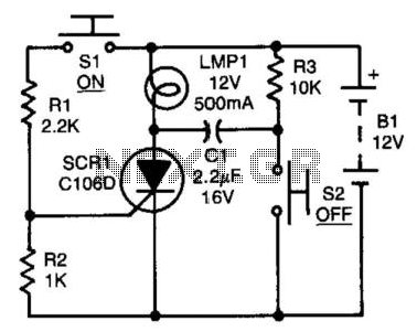
After the SCR is activated, capacitor CI charges up to nearly the full supply voltage through resistor R3 and the anode of the SCR. When switch S2 is later closed, it grounds the positive terminal of CI, causing the...