
AC polarity detection

The design of a circuit capable of detecting AC polarity without the need for a ground reference involves several key components and considerations. The circuit must be able to operate effectively within a voltage range of 120 VAC to 250 VAC, which is commonly encountered in various regions. The primary challenge lies in differentiating between the hot and neutral wires without a direct ground reference.
One potential approach is to utilize capacitive sensing techniques, which can detect the presence of AC voltage without direct electrical contact. This method can be achieved through the use of a high-gain amplifier circuit that is sensitive to the electric field generated by the AC line. The output of this amplifier can be connected to an LED indicator, which lights up when the circuit is exposed to the hot wire.
A Hall-effect sensor can also be integrated into the design to detect the magnetic field generated by the current flowing through the hot wire. This sensor can provide additional information about the wire's status, particularly in identifying whether it is under load or not. The combination of capacitive sensing and Hall-effect sensing can enhance the reliability of the circuit in distinguishing between the two conductors.
The proposed circuit can be designed to include a simple LED indicator that illuminates when the hot wire is detected, providing a clear visual indication of the wire's status. The circuit can be housed in a compact enclosure, making it suitable for installation in various electrical devices.
In summary, the circuit aims to provide a straightforward solution for detecting AC polarity without the need for a ground reference. By employing capacitive and Hall-effect sensing techniques, the design can effectively differentiate between hot and neutral wires, thereby enhancing safety and usability in electrical applications. This approach not only addresses the immediate need for polarity detection but also offers a versatile solution adaptable to different electrical configurations.It should at least detect 230 VAC but it would be cool/informative for future readers if the solution could work in US and EU (approximately 120 VAC to 250 VAC). I did find this (non-isolated!) circuit, but I can not get it to simulate (the simulator complains that it needs ground or the LED blinks on both halves of the wave).
Most current answers are leading me to believe one needs a reference. Now I`m thinking, why not create one Something like a `virtual ground` or somewhere along that line Today I read that older single-phase watt/hour-meters will run backwards if neutral and hot are reversed. Why is this and couldn`t the reason for this behavior be used in a `equivalent circuit` that detects `reverse polarity` Also, I wonder: could a hall-effect sensor be used to recognize a unloaded `hot` wire, since a hot wire clearly emits a diversity of electromagnetic fields and elf radiation Are you trying to tell the wires apart, or are you trying to identify the half of the cycle when a particular one is at a positive potential relative to the other Chris Stratton Oct 11 `12 at 3:22 I want reversed polarity/phase indicator for single phase vac, using just hot and neutral, no ground and no tranny.
I searched high and low for over a week, and the simulation indicates I`m on to something other than the known `3-led` circuit that uses ground that is of no use to me. zduk Oct 11 `12 at 3:51 Again, are you trying to tell the wires apart, or are you trying to identify the half of the cycle when a particular one is at a positive potential relative to the other Chris Stratton Oct 11 `12 at 3:53 @Chris Stratton: I`m really sorry, thought the question was clear.
I`m trying to tell the 2 ac-wires apart. Put differently, I want to know what conductor has `neutral` and what connector has `hot`. Put differently, I want a indicator if the mains wall is wired wrong (as in country`s that have a wall-outlet that has different sizes of ac-power-plugs) or if I should plug-in the power-connector the other way round (for country`s where one can plug in the connector both-way`s). Does this help zduk Oct 11 `12 at 4:07 I may be simple but I don`t see how you can identify neutral and hot without a reference ground so you can see which is closer/further away, or why the `known 3-LED circuit` is of no use to you.
EJP Oct 11 `12 at 8:12 As other posters have suggested, this can`t be done via conductive measurement alone. However, non-contact AC testers will properly differentiate line from neutral without a reference ground via capacitive sensing.
This type of hand-held tester often has a flat plastic blade at the tip. Inserting the blade in the line slot will cause the LED to glow; inserting in neutral or ground will not glow: There are a number of kits for this type of circuit, as we as many sample schematics available in a few minutes of searching (Search string: non-contact ac voltage detector circuit). They`re essentially just high gain amplifiers that drive an LED. Using this type of sensor permanently mounted near the Neutral line can serve as an indicator that your plug has been inserted the wrong way, provided that you have a reliable way (i.
e. not battery) of powering the circuit. @zduk, your question was "How can I detect AC polarity (single phase) (without the use of ground/earth) and drive a led when the polarity is reversed " This solves that problem. If you need something else, you need to clarify your question. HikeOnPast Oct 11 `12 at 4:00 I can not build this into a psu/pdu. The front/back of the device should have a simple led/neon that indicates ac polarity reversal. If however this site is intended to enquire about electronic gadgeds instead of electronic schematics, then please point me to the correct forum/stack-thingy and accept my apology`s for asking this in the wrong place.
zduk Oct 11 `12 at 4:14 I`m not ignoring your answer :) But for now I`m not ready to accept that 🔗 External reference
Related Circuits
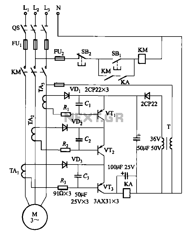
Drawing transistors that comprise the gate VTi, VT2, VT3, and similar components. The schematic involves a configuration of transistors designated as VTi, VT2, and VT3, which are integral to forming a gate structure. These transistors are typically arranged in a...
The figure illustrates a simplified representation of the Earth's dipole magnetic field, resembling that of a bar magnet. Field lines originate from the south magnetic pole and terminate at the north magnetic pole. The angle at which this field...
The simplest polarity protection technique is to connect a series diode to the power line input. The diode conducts only when the power supply is connected correctly. A series diode is an effective method for preventing reverse polarity in electronic...
Due to the small size, high precision, and sensitivity of surface acoustic wave (SAW) sensors, along with their cost-effectiveness, a SAW gas sensor has been developed. This sensor comprises a surface acoustic wave device, a sensitive membrane, and the...
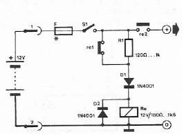
Safety polarity connection circuit design using common electronic components The safety polarity connection circuit is designed to ensure that electronic devices are connected with the correct polarity, preventing damage from reversed connections. This circuit typically employs common electronic components such...
The search loop can be constructed in various ways; however, the method presented here should provide a solid foundation. Refer to Fig. 2 as a guide for assembling the loop. The loop should be made from non-metallic and moisture-resistant...