
AC-static SPDT switch

An SPDT (Single Pole Double Throw) solid-state relay is a crucial component in electronic switching applications, enabling control over multiple loads with a single control signal. In this configuration, the relay consists of two main transistors, Q1 and Q2, along with resistors and a switch.
Upon the application of voltage to the relay, Q1 is triggered, allowing current to flow and energizing load #1. The presence of full line voltage across Q2 is essential for this operation, as it ensures that gate current flows through resistor R1, maintaining Q1 in an 'on' state. R1 serves as a gate resistor, limiting the current to Q1 and protecting it from excessive current that could lead to damage.
The operation of the relay can be altered by the position of switch S1. When S1 is closed, it activates Q2, which in turn removes the gate drive from Q1. This action effectively deactivates load #1, as Q1 turns off, and simultaneously activates load #2. This switching mechanism allows for seamless transition between loads, making the circuit versatile for various applications.
The relay's design ensures that it can handle the necessary voltage and current levels for both loads while providing isolation between the control circuit and the load circuit. This isolation is critical for protecting sensitive control electronics from high voltages or currents present in the load circuits. The use of solid-state components also contributes to faster switching times and increased reliability compared to traditional electromechanical relays.
In summary, the SPDT solid-state relay provides an efficient means of controlling multiple loads with a single control input, utilizing the properties of transistors to achieve rapid and reliable switching. Properly designed, this relay configuration can enhance the functionality and safety of various electronic systems.An SPDT solid state relay is shown. When voltage is applied Ql will turn on, activating load #1, because the full line voltage appears across Q2, supplying gate current through Rl. When SI is closed. Q2 turns on removing the gate drive from Ql and activating load #2.
Related Circuits
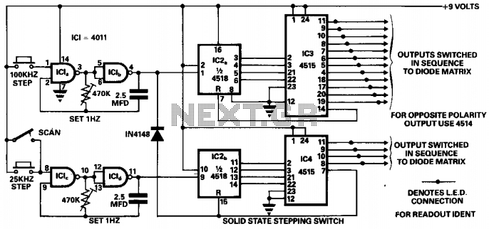
This circuit was designed to ensure safe operation of a 48-channel mobile transceiver while in motion. It incorporates oscillators that facilitate single-stepping or scanning functions. The scanning feature enables the user to sequentially check all 48 channels for occupancy,...
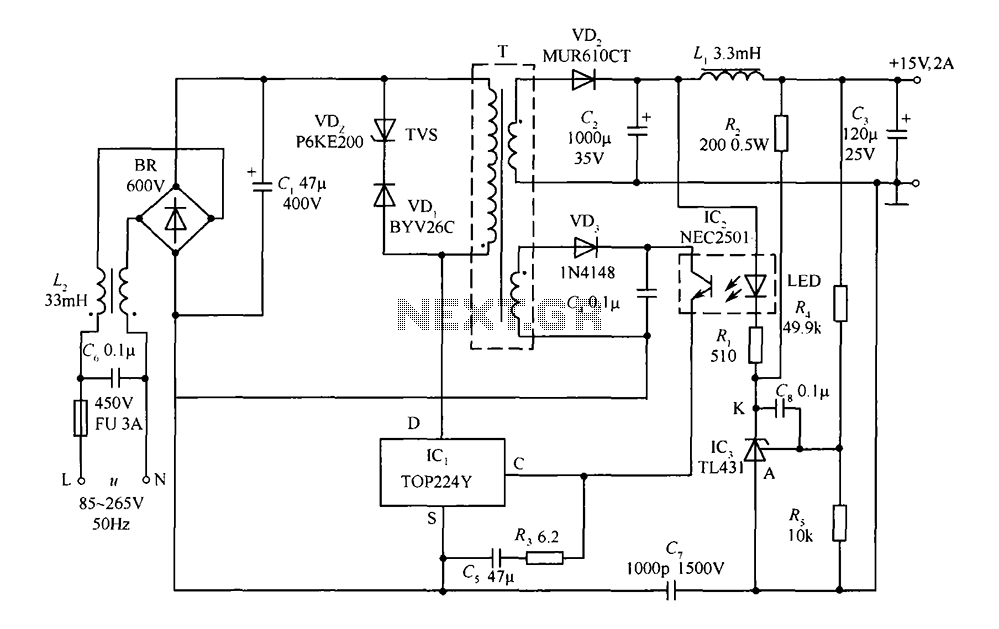
This circuit comprises a 15V TOP224Y, 2A output DC switching power supply. It utilizes three integrated circuits: IC1 is a monolithic regulator (TOP224Y), IC2 is an optocoupler (NEC2501), and IC3 is a precision voltage reference (TL431). The TL431 (IC3)...
Driving the highway with your high-beam headlights can really increase your visibility, but can be a blinding hazard for other drivers. This simple circuit can be wired into your headlight switch to provide automatic switching between high and low...
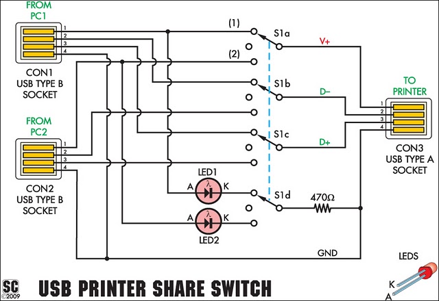
This device enables two computers to share a single USB printer or other USB devices such as an external flash drive, memory card reader, or scanner. A rotary switch is used to select the PC that will connect to...
A circuit is needed to control a couple of large AC solenoid valves and several single-phase AC motors. The line voltage is 132VAC, with the solenoids drawing 1A and the motors drawing 13A and 27A when operating. The goal...
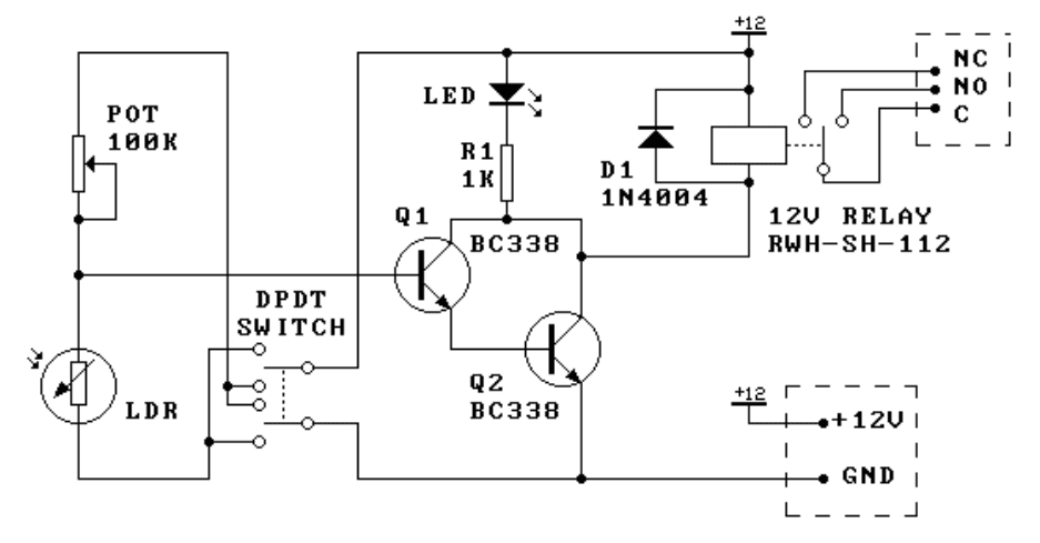
This kit is the most basic, practical circuit to build using an LDR to turn on a relay. The two transistors connected as a Darlington pair give the circuit enough sensitivity, while the trimpot gives sensitivity adjustment. The switching...