
Adc Poller Circuit

The CS5501 analog-to-digital converter employs a delta-sigma architecture, providing high-resolution signal conversion suitable for various applications. The continuous conversion mode allows for real-time signal processing; however, the lack of a start convert command necessitates a mechanism for controlled data retrieval. By integrating a dual J-K flip-flop, the circuit can be modified to enable polling, which enhances the flexibility of data acquisition.
In the asynchronous communication mode (UART), the CS5501 can efficiently transmit data over an RS-232 serial line. The use of a null character to set the flip-flop PF2 ensures that the ADC only outputs data when explicitly requested, minimizing unnecessary data transmission and power consumption. The conversion word is transmitted as two bytes, accommodating the RS-232 protocol's requirements for start and stop bits, ensuring reliable communication between devices.
The baud rate configuration, achieved through the 74HC4040 counter/divider, allows for adaptability in communication speed, ensuring compatibility with various serial communication standards. This capability is particularly advantageous in applications where the ADC's output register is utilized in synchronous-serial clock (SSC) mode. In this mode, the CS5501 can efficiently load conversion data into a serial-to-parallel register composed of two 74HC595 shift registers, enabling streamlined data handling and processing.
Overall, the integration of the CS5501 ADC with additional components such as the dual J-K flip-flop and 74HC4040 counter/divider provides a robust solution for precise and controlled data acquisition in digital systems. Because the CS5501 16-bit-delta-sigma analog-to-digital converter lacks a start convert command, it converts continuously, outputting conversion words to its output register every 1024 cycles of its master clock. However, by incorporating a standard dual J-K flip-flop into the circuit, the ADC can be configured to output a single-conversion word only when it is polled.The CS5501 converter can be operated in its asynchronous communication mode (UART) to transmit one 16-bit conversion word when it is polled over an RS-232 serial line (see figure).
A null character (all zeros) is transmitted to the circuit and sets the flip-flop PF2. The CS5501 can then output a single-conversion word, which is transmitted over the RS-232 line as two bytes with start and stop bits. The baud rate can be chosen by selecting the appropriate clock divider rate on the 74HC4040 counter/divider as the serial port clock (SLCK) for the ADC. This type of polled-mode operation is also useful when the ADC`s output register is configured to operate in the synchronous-serial clock (SSC) mode.
In this case, the converter will load one output word into a 16-bit serial-to-parallel register (two 74HC595 8-bit registers) when polled to do so (see figure).
Related Circuits
The BLW96 is a high-frequency (HF) and very high-frequency (VHF) power transistor designed for use in class A, AB, and B operated high-power industrial and military transmitting equipment. The BLW96 transistor is a crucial component in RF (radio frequency) applications,...
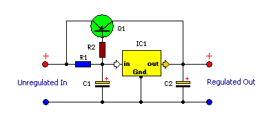
This is a compact and highly functional circuit that can be constructed on a veroboard. Voltage regulators such as the LM708 and LM317 series (among others) may occasionally require a load. The circuit utilizes voltage regulators, which are essential components...
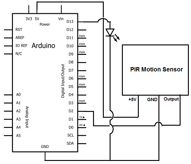
Once the motion sensor detects motion, the Arduino can be programmed to activate an LED, turn on a motor, sound a buzzer, etc. In this circuit, for simplicity, an LED will be turned on when the motion sensor detects...
Assistance is needed for the design of a timing circuit intended to activate a spark plug every 10 or 20 revolutions of a shaft. The timing circuit for firing a spark plug at specified intervals can be designed using a...
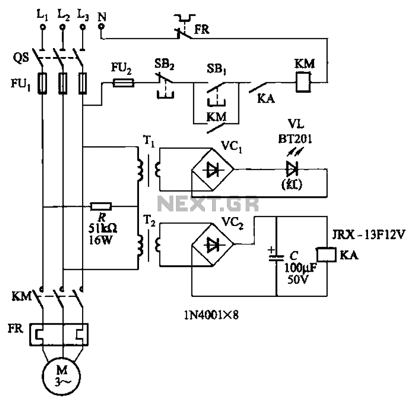
The circuit depicted in Figure 3-92 employs a dual-phase sequence protection relay for sensing. When the power supply exhibits a positive phase sequence (U, V, W), the relay KA is activated. If the power supply maintains the correct phase...
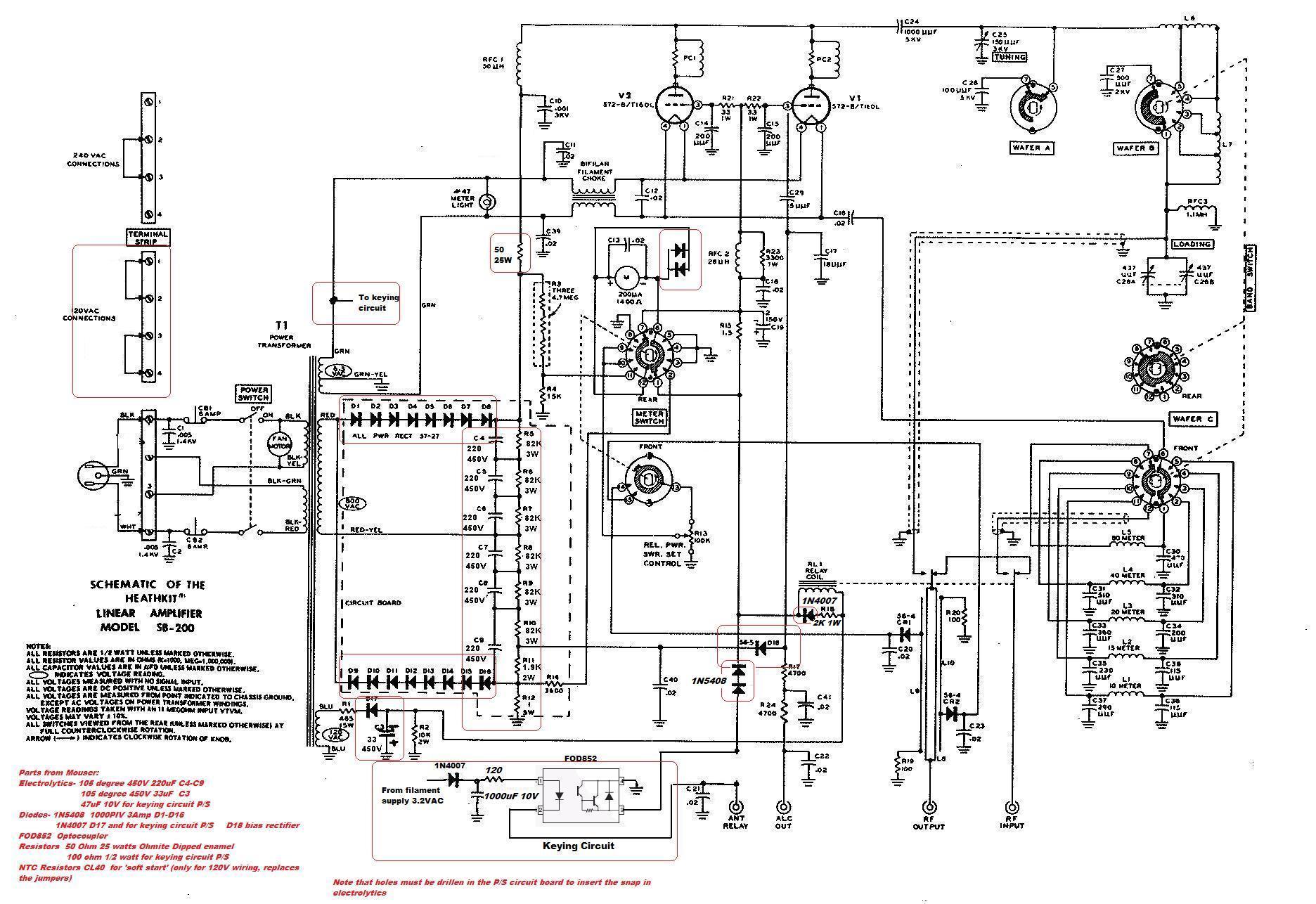
This circuit serves as a cost-effective alternative to commercially available keying circuits. It has been successfully implemented in the SB-200 amplifier. A schematic of the modified SB-200 is provided. The described circuit is designed to function as a keying mechanism...