
Advanced appliance timer

The circuit's operation hinges on the precise timing and control provided by the combination of the optical coupler, square wave generator, and divide-by-N counters. The optical coupler serves as an interface between the low-voltage control circuitry and the higher voltage required to operate the appliances. The monostable multivibrator's output pulse width can be adjusted through the selection of the resistor and capacitor values, allowing for flexibility in timing. The choice of the SN74177 as the counting mechanism provides reliable and programmable counting capabilities, allowing for various configurations based on the needs of the application.
In practical applications, this timer circuit can be employed in various household appliances, automated systems, and industrial equipment where precise timing control is required. The design can be further enhanced by integrating additional components for features such as user interfaces, remote control, or connectivity to smart home systems, making it a versatile solution for time-based automation.This project introduces important type of transducer, an optical coupler. An optical coupler together with a square wave generator and counters can be used to construct a timer for appliances. That is, an appliance can be turned on at a desired time for a specific time interval, Figure 1 shows a block diagram of such a timer.
As shown in Figure 1, the output of the square wave generator is used as a clock (trigger signal) for the divide-by-N counters. A divide-by-N counter is a digital IC that produces a single output pulse for every N input pulses, where N is an integer.
The integer N is commonly called the modulus of the counter. There are basically two types of divide-by- N counters: fixed and programmable. In Figure 1, the output of the divide-by-N Counters is then applied to a one-shot (monostable) multivibrator, the output of which in turn drives the optical coupler. The output pulse width of the controls the time an optical coupler is on. The output of the monostable multivibrator is also applied to the reset control circuit, which halts the square wave generator and also resets the circuit for restart operation.
The resistor-capacitor combination used for the monostable determines its output pulse width. When the output pulse goes high (logic 0 to 1), the optical coupler is triggered and the appliance turns on. On the other hand, when the output pulse width of the monostable goes low (logic l to 0), the optical Coupler is disabled and the appliance turns off.
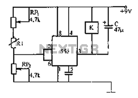
At the same time, the negative transition of the pulse also triggers the reset control circuit, which in turn shuts the square wave generator. Thus the circuit is ready for the next. Now let us see how the 3011 is used in the appliance timer. Figure 2 shows the schematic diagram of the timer, which is designed to switch an appliance on 23 minutes after the initial startup time.
The appliance remains on for approximately 12 minutes. The 556, a dual 555 timer, is used to form the astable and monostable rnultivibrators. The time between the pulses as well as the output pulse width of the timers is limited by the size and cost of the timing components. In the circuit of Figure 1, the time period of the pulse output waveform of the astable muitivibrator is T=0.
69(RA + 2RB)C = 11. 5 minutes, even though a maximum time period of approximately 20 minutes is possible. The output pulse waveform of the astable multivibrator works as a clock for the SN74177 4-bit binary counters/latches. The SN74177, a DIP, consists of four dc- coupled master-slave flip-flops, which accept frequencies of 0 to 35 MHZ at the clock 1 input and 0 to 7.
5 MHZ at the clock 2 input (see Figure 2). It is fully programmable and triggers on the negative-going edge of the clock pulse. A, B, C, and D are the data inputs and QA, QB, QC, and QD are the outputs. When the count/load (pin 1) is low, the outputs directly follow the inputs. However, when the count/load is high (logic l) and the clock inputs are inactive, the outputs remain unchanged. The clear terminal (pin 13), when taken low (logic 0), sets all outputs low regardless of the states of the clocks.
In Figure 2, the SN74177 is used as a 4-bit ripple-through counter in which output QA must be externally connected to the clock 2 input. The output of the astable multivibrator is applied to the clock 1 input. In addition, the count/load is connected to +5 V and clear is taken low each time the timer is used. In fact, this arrangement enables the 74177 to perform simultaneous divisions by 2, 4, 8, and 16 at the QA, QB, QC, and QD outputs, respectively.
That is, the outputs at QA, QB, QC, and QD will have timer periods of 23, 46, 92, and 184 minutes. However, only the QA output is used in Figure 2. To achieve longer time periods, output QD of the 74177 can be used to clock the next SN74l77, and so on. In addition, by using all four outputs of the 74177, three more appliances can be co 🔗 External reference
Related Circuits
The 555 timer integrates both analog and digital functions within a scaled integrated device. Typically manufactured using a bipolar process, it is designated as the 555 timer, while the CMOS version is referred to as the 7555. In addition...
The camera has been wired with external shutter leads, and a method is needed to trigger them. These leads must be connected together via a relay at regular intervals, approximately every 2 seconds, starting from launch. A 555 timer...
Half of a Motorola MG14538B dual precision retriggerable monostable multivibrator is utilized to create an extended on-time timer circuit. This type of circuit can function as a switch debouncer. Such circuits are commonly implemented in digital applications, where every...
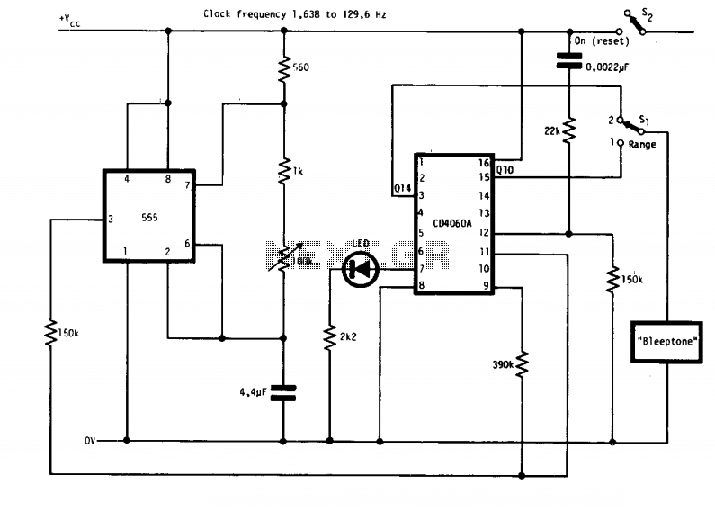
The circuit features two timing ranges: from 10 seconds to 5 minutes and from 1 minute to 80 minutes. It is powered by a 9-V battery. An LED is connected in a manner that allows for a consistent flashing...
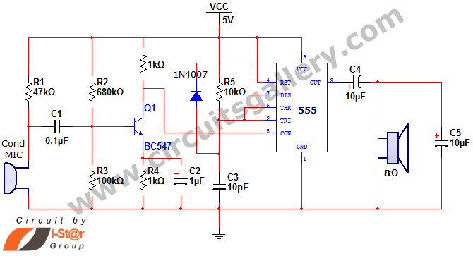
This document discusses a simple project utilizing the 555 timer IC. The 555 timer IC can be configured as an audio amplifier using an astable multivibrator configuration. It performs pulse width modulation (PWM) on an audio signal. The current...
This circuit demonstrates the application of a 4017 CMOS decade counter to construct a timer circuit. The push-button switch S1 discharges capacitor C1 through resistor R2. Upon releasing S1, capacitor C1 charges through resistor R1, generating a rising edge...