
Alternating current voltage amplifier transistor

The circuit described involves an AC voltage amplifier using a transistor, which is a fundamental component in analog electronics. The AC path indicates that the circuit is designed to amplify alternating current signals, which are characterized by their periodic nature. The low internal resistance of the AC supply voltage source suggests that it can effectively drive the circuit without significant voltage drop, allowing for accurate signal amplification.
In this configuration, the concept of AC ground is crucial. By defining the AC ground at the voltage terminal Vcc as 0 volts, the circuit can maintain a stable reference point for AC signals. This reference point is essential for ensuring that the amplified output accurately reflects the input signal variations. The emitter terminal (e) of the transistor plays a vital role in establishing this AC ground connection. The use of capacitor C7 facilitates this connection, allowing AC signals to pass while blocking any DC component that may be present.
Capacitor C7 serves as a coupling capacitor, which is critical in AC applications. It prevents DC bias from affecting the AC signal path while allowing the AC signals to flow from the emitter to the AC ground. This ensures that the transistor operates correctly within its active region, enhancing the linearity and fidelity of the amplification process.
Overall, the described circuit effectively utilizes an AC path for voltage amplification, leveraging the properties of the transistor and the strategic placement of capacitors to achieve optimal performance in AC signal processing.Alternating current voltage amplifier transistor AC path. In AC analysis, since the internal resistance of the AC supply voltage source is small, it corresponds to the short-ci rcuit signal, so that the alternating voltage terminal Vcc is ov, called AC ground. AC ground and the actual ground can be regarded as the same point, the emitter (e) via the capacitor C7 is AC ground,
Related Circuits
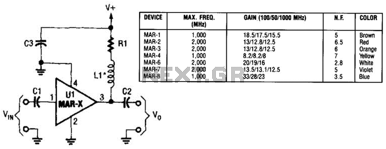
In this basic MAR-x-based circuit, both the input and output consist of a single DC-blocking capacitor (C1 for the input and C2 for the output, respectively). The DC power supply network, which includes L1 and R1, is connected to...
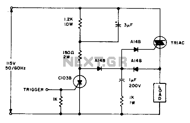
The triac will be activated at the beginning of the positive half cycle due to the current flowing through the 3 µF capacitor, provided that the C103 SCR is in the off state. The load voltage subsequently charges the...
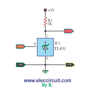
This is a simple pressure level check circuit, utilizing the integrated circuit TL431. It operates with a power supply of 5 volts for the digital circuit. The general feeding signal is... The circuit is designed to monitor pressure levels by...
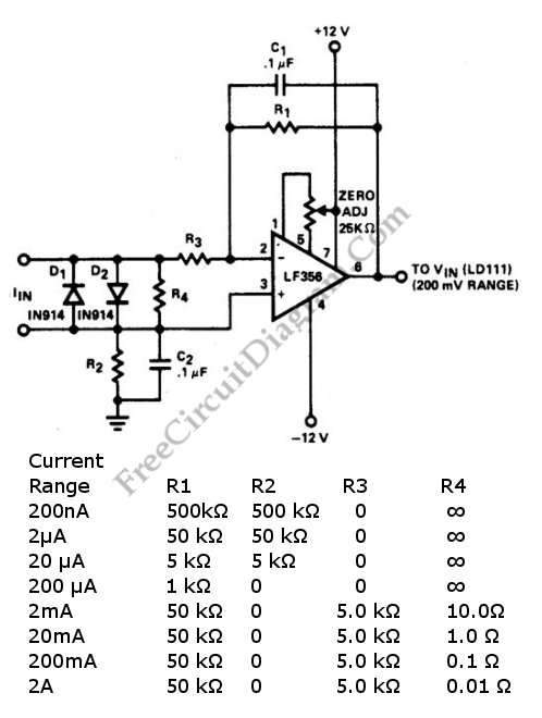
A current-to-voltage converter circuit can be constructed using a single resistor. This design is straightforward, as any current flowing through a resistor will naturally generate a voltage. A current-to-voltage converter, also known as a transimpedance amplifier, is primarily utilized to...
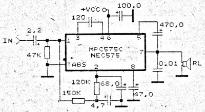
An amplifier circuit is particularly well-suited for use in confined spaces, such as within vehicles. It requires a voltage supply ranging from 9 Volts to a maximum of 17 Volts. This amplifier circuit utilizes the IC MPC575C, which is...
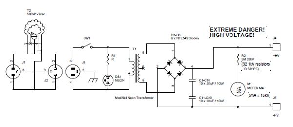
Transformers designed for powering large neon signs are cost-effective and highly reliable. Typically, the secondary winding is center-tapped, which restricts the full utilization of its peak-to-peak output in scenarios where one terminal must be grounded. In the power supply...