
Electric shaver circuit

The electric shaver circuit operates by utilizing a buck converter topology to efficiently step down the voltage from the power supply. The buck capacitor (C) plays a crucial role in smoothing out the voltage and ensuring stable operation of the circuit. The diode (VD) is essential for allowing current to flow in one direction, thereby preventing backflow that could damage the circuit components, particularly when charging the nickel-cadmium batteries.
The integration of an LED display serves as a visual indicator of the shaver's operational status, enhancing user interaction. The LED illuminates when the device is powered on, providing a clear signal that the shaver is ready for use. The toggle switch (S) enables the user to easily control the power to the motor, which is responsible for the rotational motion necessary for effective shaving.
When the shaver is not in operation, it remains connected to a 220V power source for charging. This design choice ensures that the nickel-cadmium batteries are continuously charged and ready for use, promoting convenience and ensuring the device is always operational when needed. The motor, upon activation, engages the shaver head, allowing for efficient hair removal through its rotational motion. The overall circuit design emphasizes safety, efficiency, and user-friendliness, making it suitable for everyday grooming needs.Electric shavers thorn circuit shown in Figure 1-17. Shown by the capacitance C buck, buck capacitor C is lyF/450V, pass through the diode VD, to 1.2V nickel-cadmium batteries. After Buck Island for the display element to the LED. When not in use, connected to the 220V power charger, so when used, toggle switch S, and the motor is turned on, the motor drives the shaver piece rotation.
Related Circuits
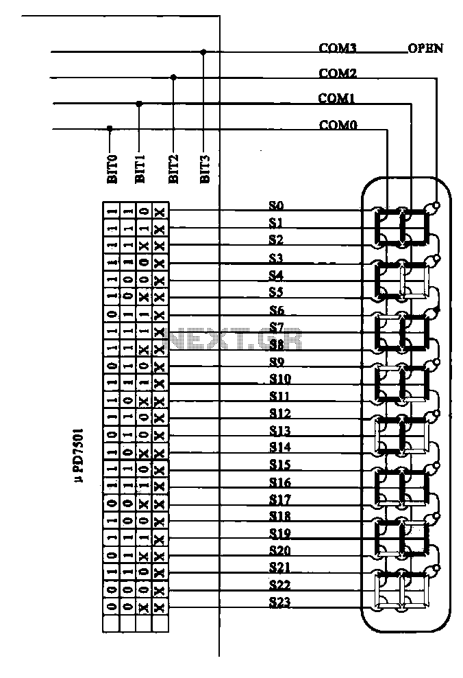
Examples of the structure of several liquid crystal display drive circuit CPU tubes. Liquid crystal display (LCD) drive circuits play a critical role in controlling the operation of LCD panels, which are widely used in various electronic devices. These circuits...

This circuit is the simplest inductive balancing metal detector (IB, Induction Balance) that can be constructed. The LB metal detection method offers satisfactory depth of penetration and effectively distinguishes between iron-based and noble metallic objects. While several metal detectors...
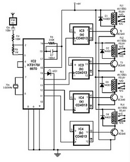
This project utilizes DTMF (dual-tone multi-frequency) signals, commonly used in telephones for dialing digits, as control codes. The DTMF tones are employed for frequency modulation of the carrier signal. At the receiver unit, these frequency-modulated signals are intercepted to...
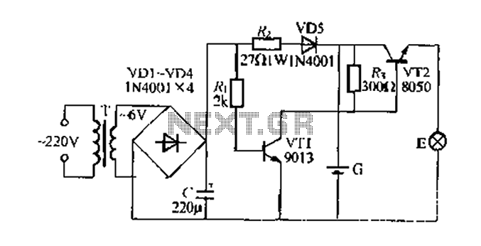
Figure 282 illustrates a simple emergency lamp circuit designed to activate during a power outage. The circuit utilizes a transformer (T) for voltage stepping, diodes (VD1 to VD4) for rectification, and a capacitor (C) for smoothing the output. During...
The 27MHz crystal oscillator circuit is illustrated in the figure. Resistors R1, R2, and R3 serve as biasing resistors, while capacitor C6 functions as a bypass capacitor. The voltage division circuit consists of capacitors C1, C3, C4, and C2,...
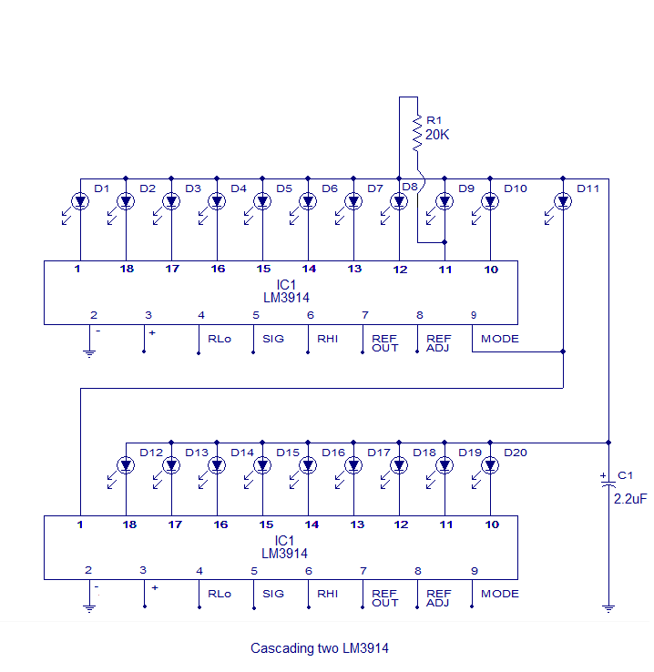
The core of this circuit is the LM3914 from National Semiconductor. The LM3914 is capable of sensing voltage levels and can drive a display of 10 LEDs in either dot mode or bar mode. The selection between bar mode...