
Amp Voltage Follower

The described circuit utilizes a power operational amplifier (op-amp) intended for low-frequency applications, specifically up to 300 Hz. Power op-amps are commonly employed in applications requiring high output current and voltage gain. This circuit's design includes a fixed flow regulator, which, while offering stability, poses difficulties in implementing conventional protection mechanisms.
To address the issue of excessive current flow through the load, the circuit incorporates a voltage limiting feature. This is crucial in preventing damage to both the load and the op-amp itself. The voltage regulator is designed to maintain a consistent output voltage; however, without adequate protection, it can be susceptible to overload conditions.
The recommended approach includes integrating thermal limiting circuitry alongside the voltage regulator protection. Thermal limiting is essential in preventing overheating, which can lead to failure in the op-amp and associated components. This can be achieved by using temperature sensors that monitor the op-amp’s junction temperature, triggering a shutdown or reducing the output current when a predefined temperature threshold is reached.
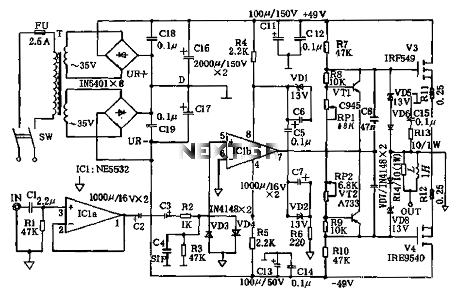
The schematic drawing provides a visual representation of the circuit configuration, showcasing the op-amp, voltage regulator, current sensing resistors, and thermal limiting components. Key elements such as feedback loops, input and output connections, and power supply configurations should be clearly marked to ensure proper understanding and implementation of the circuit.
In summary, this power op-amp circuit is designed for low-frequency applications with an emphasis on protecting the flow regulator from excessive current and thermal overload. The combination of voltage limiting and thermal protection circuitry enhances reliability and performance, making it suitable for various electronic applications.A simple power op amps to 300 Hz operation. One type of circuit is more difficult to protect the flow regulator. Because it`s been fixed, the normal protections are not working. Circuit to limit the voltage regulator allows the flow of excessive current flow through the load. About the only method that protects both the regulator protection and th ermal limiting circuitry is encouraged. Here is a schematic drawing: 🔗 External reference
Related Circuits
This circuit is a dual voltage regulated power supply, +12, -12, 0 volt. It uses the 7812 and 7912 regulators. You need a 18VCT, 1A transformer at input. More: Caution: Input / Ground are reversed between the 7812 and...
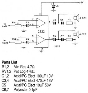
A 1W stereo headphone amplifier circuit, based on the TDA2822, is designed for portable players, radios, and other electronic devices that utilize headphones as the output. The TDA2822 is a dual audio power amplifier IC capable of delivering up to...
The JCM800 power amplifier has a rich heritage, drawing from classic amplifiers such as the Fender Bassman 5F6-A, the Marshall JTM45, the Model 1962 "Bluesbreaker," and the Model 1987 "Plexi." It features significantly enhanced power supply filtering compared to...
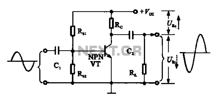
A common emitter amplifier functions as a signal amplification unit by utilizing a common emitter configuration, which inverts the output signal. This operation can be analyzed by observing the input signal waveform. During the first quarter of the period,...
Many times we needed to use a simple circuit of preamplifier, with few components and facility of made. This circuit uses an opamp, the Motorola, TCA5550, that contains a double amplifier, as outputs for the adjust of volume, balance,...
The amplifier circuit presented in this paper introduces a floating power supply aimed at increasing output power. The output power of the amplifier is influenced primarily by the final stage amplifier supply voltage. The circuit's principle is illustrated in...