
Amplifier Thermal Protection

The described project involves a thermal management system for a bi-amp audio unit, which employs a fan cooling mechanism to prevent overheating. The system is activated when the internal temperature of the amplifier reaches a predetermined threshold, triggering the fans to operate. This method is particularly beneficial during high-volume listening sessions on hot days, ensuring that the amplifier remains within safe operating temperatures.
The fans remain operational until the amplifier is powered down, providing continuous cooling during critical periods. Although the design is characterized as crude, it has proven to be effective in protecting the amplifier from thermal damage. The noise generated by the fans can be mitigated by reducing their operating voltage, which contributes to a quieter operation while still maintaining adequate cooling.
In addition to the active cooling system, a passive safety feature is proposed, which involves automatically disconnecting power to the amplifier when overheating is detected. This serves as a fail-safe mechanism, ensuring that the amplifier is protected even in scenarios where it may be left powered on for extended periods. Implementing this backup system would enhance reliability and prevent potential damage due to prolonged overheating, particularly for users who frequently operate their amplifiers at high volumes.
For the implementation of such a system, a temperature sensor can be integrated into the amplifier's circuitry, providing real-time temperature monitoring. A microcontroller or a simple relay circuit could be employed to control the activation of the fans based on the temperature readings. Additionally, a thermal cutoff switch could be integrated into the power supply line of the amplifier, which would disconnect power if the temperature exceeds a critical limit, thereby providing an extra layer of protection. This dual approach to thermal management ensures that the amplifier operates efficiently while safeguarding against potential overheating scenarios.This project is really a mixture of ideas, some simple, and others even simpler. The system I have installed in my biamp unit is fan cooling. Once a preset temperature is reached, the fans start, and remain on until the amp is turned off again. This is crude, but very effective. It only operates if I am listening LOUD on a very hot day, which means that the fans have probably only operated about 5 times in their life.
I do know about it when they operate because they are fairly noisy (although I have reduced the operating voltage which quietens them down a bit), but at least I know that the amp is protected. Even simpler is to just switch off the power when the amp overheats. I would use this as a backup to the thermo-fan or fan controller if I left the amp powered on all the time. While I don`t do this, a lot of people do, and although it does waste a 🔗 External reference
Related Circuits
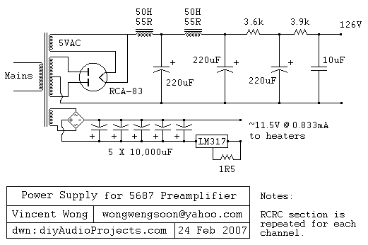
The RCA-83 rectifier utilizes 5VAC for the filament supply. The heaters for the 5687 tubes are powered by a full bridge rectifier consisting of MUR860 diodes, followed by five 10,000µF Elna capacitors. Current regulation is achieved through an LM317...
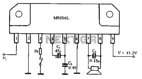
Figure 1-44 illustrates a dedicated BTL (Bridge-Tied Load) amplifier circuit, which consists of two single amplifiers. The relevant components are integrated into the circuit, simplifying the connections. The circuit operates at a power supply voltage of 13.2V and can...
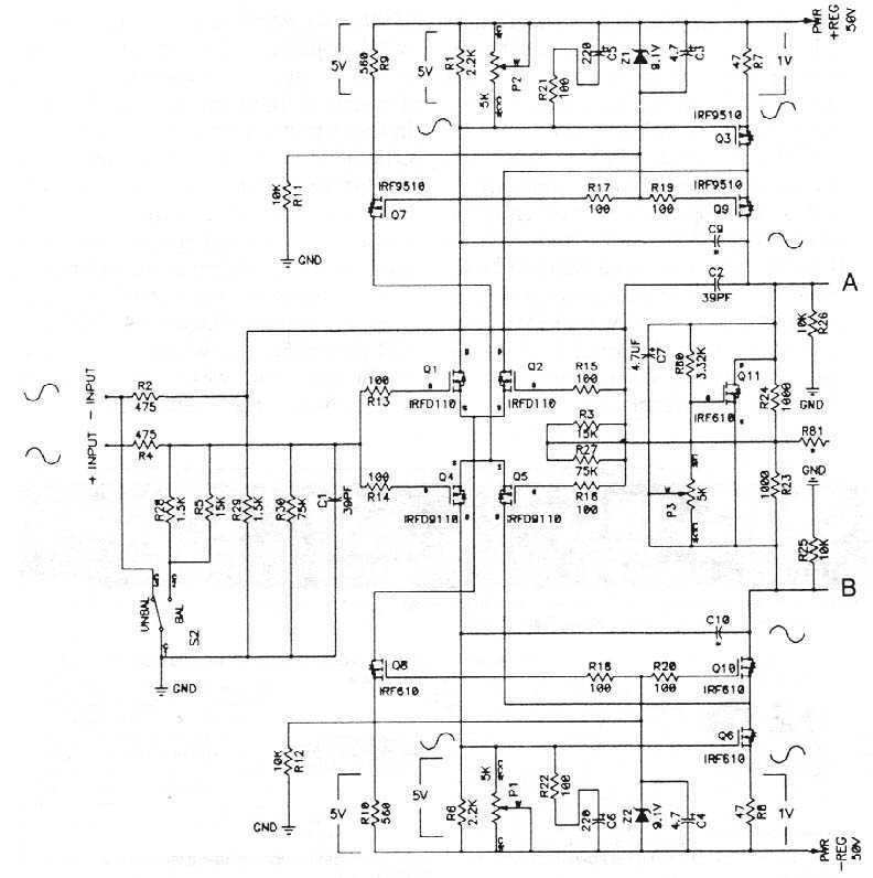
The MOSFETS we are dealing with are three terminal devices which are used to control electron flow in a circuit. Two of the pins (the source and drain) pass the current, and the third pin (the gate) is used...
The CXG1024N is a high-power antenna switch MMIC designed to connect a transmitter/receiver (TX/RX) to one of four antennas. This integrated circuit (IC) is fabricated using Sony's GaAs J-FET process and operates with a single positive power supply. The CXG1024N...
Amplifying weak radio signals presents the challenge of also amplifying noise. The ability to receive signals is contingent on the level of background noise, which can include man-made interference or static. In this design, the RF signal first encounters...
The total gain of the car antenna amplifier is approximately 30 dB, with an input impedance of around 10 kΩ at 30 MHz. The amplifier should be mounted directly at the base of the antenna to prevent signal losses...