
OverVoltage Protection Circuit

This overvoltage protection circuit, commonly referred to as a crowbar circuit, serves as a critical safety mechanism in electronic systems to prevent damage from voltage surges. It is particularly useful in scenarios where sensitive components may be exposed to transient voltages that exceed their rated limits.
The basic configuration of a crowbar circuit typically includes a voltage reference, a triggering device (such as a thyristor or SCR), and a fuse or circuit breaker. When the input voltage exceeds a predetermined threshold, the voltage reference activates the triggering device, which then creates a short circuit across the power supply. This action diverts excess voltage away from the load, effectively "crowbarring" the voltage to a safe level.
Key components of the circuit include:
1. **Voltage Reference**: This component sets the threshold voltage at which the protection mechanism is activated. It can be implemented using zener diodes or dedicated voltage reference ICs.
2. **Thyristor (SCR)**: The thyristor acts as the main switching element in the circuit. Once triggered, it remains in the conducting state until the current flowing through it falls below a certain level, providing a fast response to overvoltage conditions.
3. **Fuse or Circuit Breaker**: This is included to protect the circuit from prolonged overvoltage conditions. If the thyristor conducts for an extended period, the fuse will blow or the circuit breaker will trip, disconnecting the load from the power source.
4. **Load**: The device or circuit being protected from overvoltage conditions.
5. **Snubber Circuit**: In some designs, a snubber circuit may be added across the thyristor to absorb voltage transients and protect the thyristor from voltage spikes during turn-off.
The overall design should ensure that the crowbar circuit operates reliably under varying load conditions while providing rapid response to voltage surges. Proper selection of components and their ratings is essential to ensure that the circuit can handle the expected surge currents without failure. Additionally, thermal management considerations must be addressed to prevent overheating of the thyristor during operation.
This circuit is widely used in power supplies, industrial equipment, and consumer electronics to enhance the durability and reliability of electronic systems against voltage anomalies.This overvoltage protection or crowbar protection circuit is used where we need protection against high voltage surge. The circuit has a few components, it.. 🔗 External reference
Related Circuits
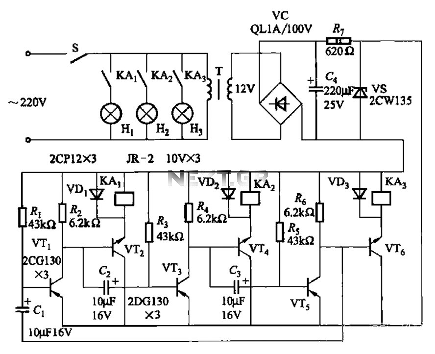
The transistors VTi, VT3, and VTs, along with the RC components, form three distinct multi-resonator oscillators. The oscillation frequency levels are dependent on the values of Ri, R3, Rs, and Cl, as well as Cz and C3s. The circuit comprises...
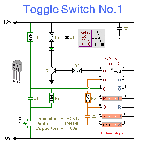
This simple circuit will energize and de-energize a relay with the push of a button. Pressing the button once will energize the relay, while pressing it a second time will de-energize the relay. The accompanying circuit provides a solid...
A substation capable of consuming 100 MVA with 375 kVA, 60 Hz input and 132 kV at 50 Hz using the same power. The challenge is to convert the 60 Hz input to 50 Hz, including a wiring diagram. To...

A simple 3.25W constant voltage/constant current (CV/CC) charger can be designed using the LinKSwitch family IC manufactured by Power Integrations. This electronic circuit project is intended to provide a 5-volt output with a maximum current of 650mA. The 3.25W...
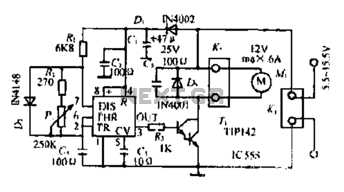
Most governors utilize pulse width modulation (PWM) and pulse position modulation (PPM) in their circuits. The 555 timer is commonly used in these applications. The pulse width is typically fixed at 0.5 milliseconds, which is essential for the functioning...

Electric shaver motor drive circuit. It illustrates a typical motor drive circuit for an electric shaver. AC 220V is used to charge the battery through the charging circuit, which also provides power to the motor. After activating the charge-on...