
Analog Compensation Circuit for PT100 RTD Temperature Sensor

Compensation for the nonlinearity of a PT100 RTD (Resistance Temperature Detector) is essential for achieving accurate temperature measurements. The PT100 RTD exhibits a nonlinear response to temperature changes, which can lead to measurement errors if not properly addressed.
Digital methods for linearization often involve the use of microcontrollers or digital signal processors (DSPs) that apply algorithms to correct the nonlinear response. These algorithms can include polynomial fitting, lookup tables, or spline interpolation to map the nonlinear characteristics of the PT100 to a linear output. The implementation typically requires an analog-to-digital converter (ADC) to sample the RTD output, followed by processing the data using the chosen algorithm, and finally outputting the corrected digital signal.
Analog methods may involve the use of operational amplifiers (op-amps) configured in specific arrangements to create a linear output based on the RTD resistance. This can include using resistor networks or feedback loops to shape the response curve. The choice between digital and analog methods depends on the specific application requirements, including factors such as cost, complexity, and desired accuracy.
In summary, both digital and analog techniques are viable for compensating the nonlinearity of PT100 RTDs, with each method offering distinct advantages and considerations for implementation.There are some digital and analog that can be used for compensating a PT100 RTD nonlinearity. We can implemented the digital linearization by implementing the. 🔗 External reference
Related Circuits
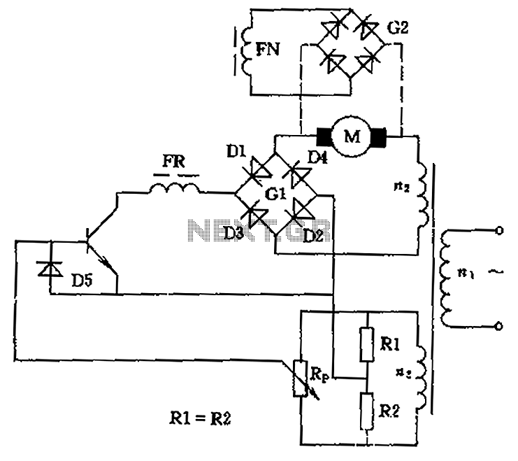
The circuit is designed to control the speed and direction of low-power DC motors, including series and shunt motors. It utilizes a rectifier bridge (G1) connected in series with the motor and linked to the secondary winding (n2) of...
This acoustic sensor was originally developed for an industrial application (monitoring a siren), but it will also find many domestic applications. The sensor is designed with safety of operation as the top priority, meaning that in the worst-case scenario...
The following circuit illustrates an Ultrasonic Sensor Circuit Diagram. This circuit is based on the MAX232 IC. Features include a quiescent current of 150mA. The Ultrasonic Sensor Circuit utilizes the MAX232 integrated circuit, which is primarily designed for converting signals...
A crystal oscillator circuit is a straightforward oscillator circuit that can be easily understood through its schematic diagram. It serves as a replacement for a conventional oscillator network, which typically consists of an LC combination. This simplicity is also...
This circuit is a difference amplifier. It functions as an inverting amplifier that enables the subtraction of two voltages, effectively performing a summation. The difference amplifier is a fundamental circuit configuration in analog electronics, primarily used for amplifying the difference...
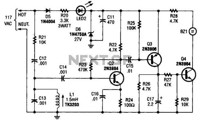
The baby-alert receiver consists of three transistors: Q2, configured as a high-gain linear amplifier; Q3, functioning as both an amplifier and detector; and Q4, which operates primarily as a switch. Additionally, there are several other components involved. The system...