
Analog frequency meter circuit

The described circuit functions as a frequency measurement tool, utilizing a combination of capacitors and an operational amplifier configuration. The frequency measurement range is established through the selection of capacitors C1 to C6, which allow for tuning the circuit to the desired frequency. The frequency range of 1.5 kHz to 500 kHz indicates that the circuit is suitable for various applications, including audio signal processing and communication systems.
Transistor T1, acting as an integrator, plays a critical role in converting the input frequency signal into a corresponding voltage output. The load resistor of 15 kΩ is essential for setting the gain and ensuring stable operation of the integrator. The adjustable resistors R1 to R6 provide flexibility in tuning the circuit parameters, allowing for precise adjustments based on the specific application requirements or input signal characteristics.
The input signal range of 4 to 10 V (peak-to-peak) indicates that the circuit is designed to handle moderate signal levels, making it suitable for interfacing with various signal sources without the need for extensive signal conditioning. Overall, this frequency measurement circuit is designed with versatility and precision in mind, enabling effective frequency analysis across a wide range of applications.The circuit can measure the frequency between 1. 5kHz ~ 500kHz by connecting C1 ~ C6 different capacitors. The maximum frequency is up to 1MHz. Transistor T1 can be used as the integrator, and its load resistor is 15k © resistor and R1 ~~ R6 adjustable resistors. Integrator`s input signal is about 4 to 10V ( peak - peak value). 🔗 External reference
Related Circuits
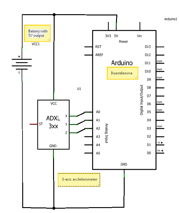
A circuit diagram illustrating the connection of an accelerometer to an Arduino board and an external power source. The circuit diagram depicts the integration of an accelerometer with an Arduino microcontroller, providing a clear representation of how these components interact...
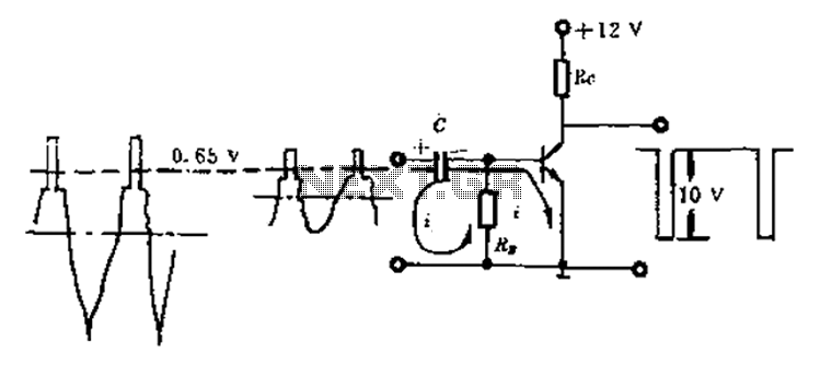
Amplitude separation circuit. A typical amplitude separating circuit is composed of a transistor, capacitance C, and resistances RB and RC. The input signal is a composite video signal, typically with a peak-to-peak voltage of about 2V. The output signal...
This decibel meter circuit responds to sound pressure levels ranging from approximately 60 to 70 dB (decibels). The sound is captured by an 8-ohm speaker and amplified using a transistor stage along with an LM324 operational amplifier section. A...
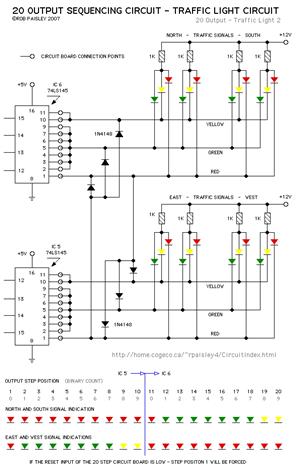
The current application involves the use of the VHDL hardware description language for designing a traffic light system controller circuit. This design is implemented within the Altera MAX PLUS EDA software environment, which facilitates compilation, simulation, and programming for...
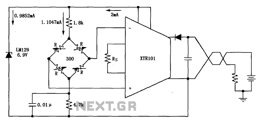
The circuit utilizes the LM129 voltage regulator to produce a 6.9V voltage reference, supplying a current of 1.0147mA from the 6.9V reference voltage to the bridge. The bridge may consist of varistor-type pressure sensors. The LM129 voltage regulator is a...
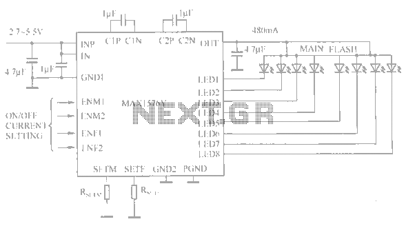
The circuit utilizes the MAX1576Y charge pump white LED driver, capable of supplying a total current of up to 480mA across two groups (n = 4 white LEDs). Each white LED in the flashing group can draw a maximum...