
Symmetrical division circuit diagram

The 4013 integrated circuit contains two D-type flip-flops that can be configured to operate in an astable multivibrator mode. In this configuration, the flip-flops continuously toggle between high and low states, producing a square wave output. This square wave signal serves as a clock pulse for various digital circuits and applications.
The astable multivibrator setup involves connecting the output of one flip-flop to the clock input of the other. This arrangement effectively divides the input frequency by two, allowing the circuit to produce an output frequency that is half of the input frequency. The symmetrical nature of the output ensures that the high and low states are equal in duration, resulting in a duty cycle of 50%.
To achieve the desired frequency, external resistors and capacitors are connected to the flip-flops, determining the timing characteristics of the oscillation. The frequency of oscillation can be calculated using the formula:
\[ f = \frac{1}{2 \times R \times C} \]
where \( R \) represents the resistance and \( C \) represents the capacitance in the timing network. By adjusting these components, the output frequency can be fine-tuned for specific applications.
The 4013 D-type flip-flops are suitable for various digital applications, including frequency dividers, pulse generators, and clock signal generation. Their versatility and reliability make them a valuable component in digital circuit design.4013 pairs of D-type flip-flop in the astable multivibrator is used as a binary divider output, will produce the output frequency of the multivibrator frequency symmetrical hal f 50/50.
Related Circuits
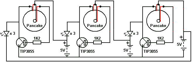
When working with these circuits, a light meter was purchased to eliminate the uncertainty in assessing light levels, as the human eye is not very reliable for this purpose. In electronic circuit design, particularly when dealing with light-sensitive applications, the...
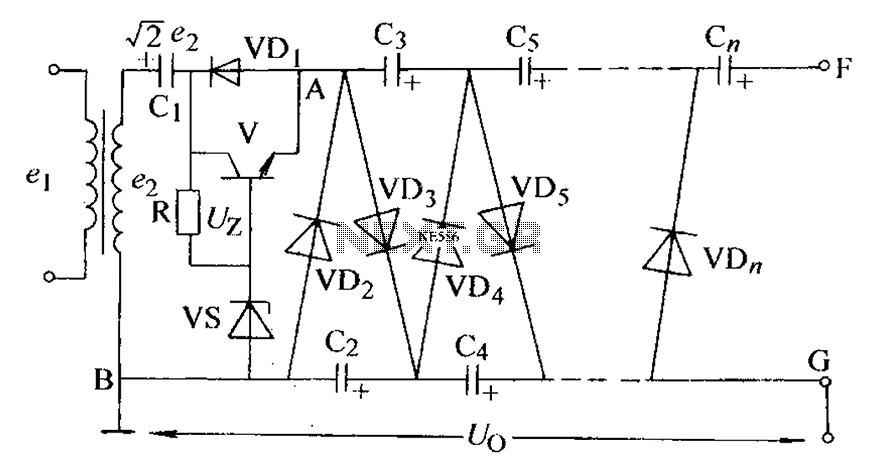
The circuit is an adjustable output voltage regulator type rectifier. It allows for obtaining peak voltage at odd multiples when the output voltage is taken from the circuit feedback (FB). Additionally, the lower point of the capacitor (CB) can...
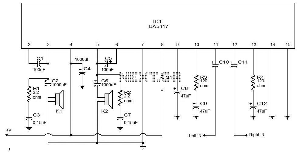
The BA5406 is a dual OTL (output transformerless) monolithic power integrated circuit (IC) featuring two high-output speaker amplifier circuits. It operates effectively with a supply voltage (Vcc) of 12 V and a load resistance (Rl) of 3 Ohms. At...
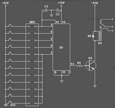
The Digital Combination Lock Circuit is a schematic for a simple electronic combination lock utilizing the LS7220 integrated circuit (IC). This password-protected digital lock can activate a relay to control any device by entering a preset combination of four...
JG series of photoelectric relay circuit. To ensure reliable operation, a Schmitt trigger circuit has been incorporated. These circuits function similarly; when light strikes the photosensitive component, its internal resistance decreases, activating the transistor VT and subsequently energizing the...
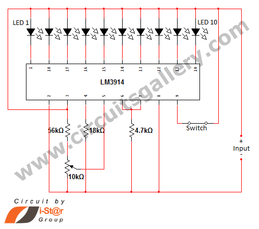
In various situations, it is necessary to indicate the amount of battery charge using methods such as LED dot displays or LED bar displays. This circuit utilizes the LM3914 integrated circuit to serve as a battery charge indicator with...