
Analogue Ohm meter
The described circuit functions as a simple ohm meter, designed for ease of construction and operation. The core of the circuit is a transistor (T1), specifically a BC 547B, which operates in a constant current mode. The current flowing through T1 is adjustable by selecting different emitter resistors through switch S1, allowing the user to choose between different measurement ranges.
The circuit employs a resistor (Rx) across which the resistance to be measured is connected. The constant current flowing through T1 generates a voltage drop across Rx, which is proportional to the resistance value according to Ohm's Law (V = I * R). This voltage drop is then measured by a meter (M), which is calibrated to read from 0 to 15 volts. The output reading on the meter directly correlates to the resistance value, which can be calculated as the resistance range multiplied by the meter reading in volts.
The circuit also includes several resistors (R1, R2, R3, R4, and R5) with specific values that help set the current levels and ensure proper operation across the chosen measurement ranges. R1 is a 1.5 kOhm resistor, R2 is an 820 kOhm resistor, R3 is an 82 kOhm resistor, R4 is an 8.2 kOhm resistor, and R5 is an unspecified value of 820 Ohms, which may serve as a load or part of the current limiting setup.
Diode D1, a 9.1 V zener diode, is used to provide voltage regulation within the circuit, ensuring that the voltage supply remains stable for accurate measurements. D2 is a germanium diode, which can be replaced with alternatives such as a 90 or OA 118, and it plays a role in the circuit's overall functionality, likely in protecting against reverse polarity or in signal conditioning.
Overall, this simple ohm meter circuit is effective for measuring resistance values in a compact form, with the added flexibility of range selection through the use of different emitter resistors.This is a simple ohm meter that is small to build. The circuit operates with a constant current around T1. The current depends on the emitter through S1 can be chosen. These are the ranges of the meter. The constant current through T1 causes a voltage drop across Rx, the measured resistance. This voltage is measured by M. D2 is a germanium diode. You can try a 90 or OA 118 using AA. The resistance value is the range times the meter reading in volts. R1 = 1.5 kOhm R2 = 820 kOhm R3 = 82 kOhm R4 = 8.2 kOhm R5 = 820 ? D1 = 9.1 V zener D2 = germanium diode T1 = BC 547B M = meter 0-15 V 🔗 External reference
Related Circuits
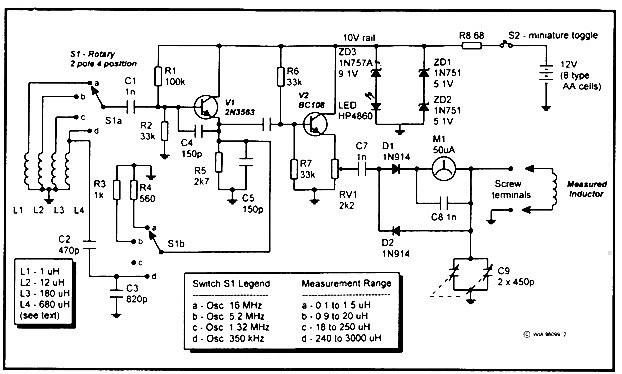
This instrument measures inductances from 0.1 microhenry to 3 millihenries, divided into four ranges set by a switch. It operates from 12 volts and is powered by eight AA type cells attached to the unit. Initially, Drew Diamond's unit...
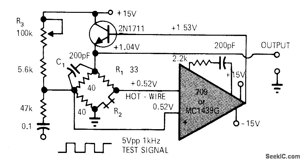
A simple operational amplifier (op-amp) circuit combined with a transistor creates a reliable hot-wire anemometer for measuring the flow of gases or liquids. Resistor R2 is heated above ambient temperature within a Wheatstone bridge configuration that includes an overheat...
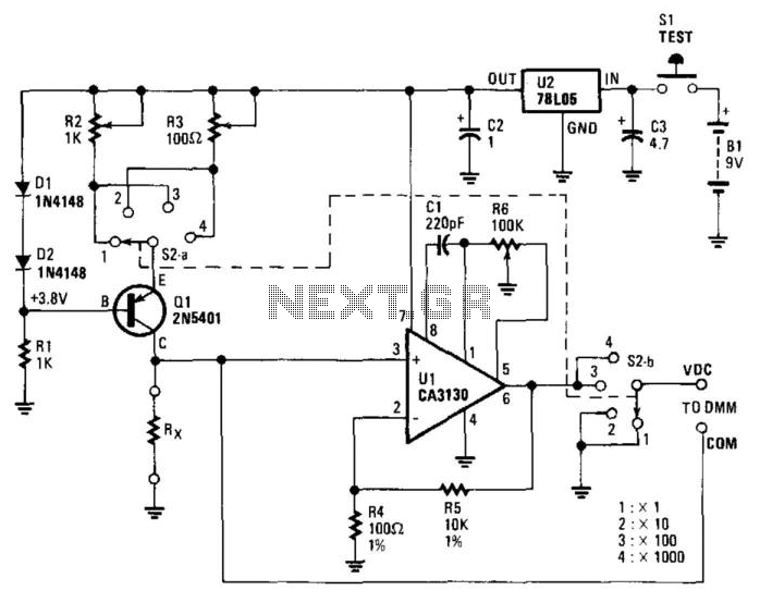
The circuit includes a 5-V regulator, a constant-current source (D1, D2, and Q1), and an operational amplifier (op amp) gain stage (U1). Power is supplied by a 9-V battery, which is regulated to +5 V DC by a three-terminal...
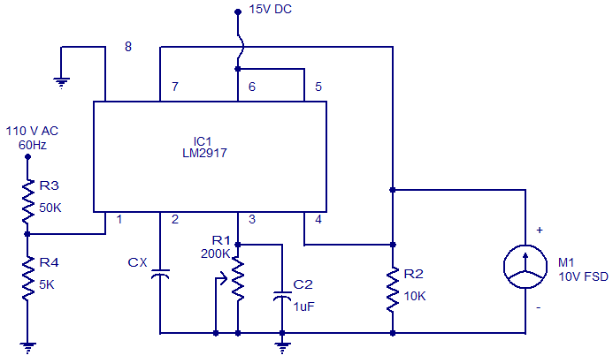
The circuit diagram of a simple capacitance meter using IC LM2917 is illustrated. The LM2917 is a high-gain monolithic frequency-to-voltage converter IC from National Semiconductors. While the primary application of the LM2917 is in tachometers, it can also be...
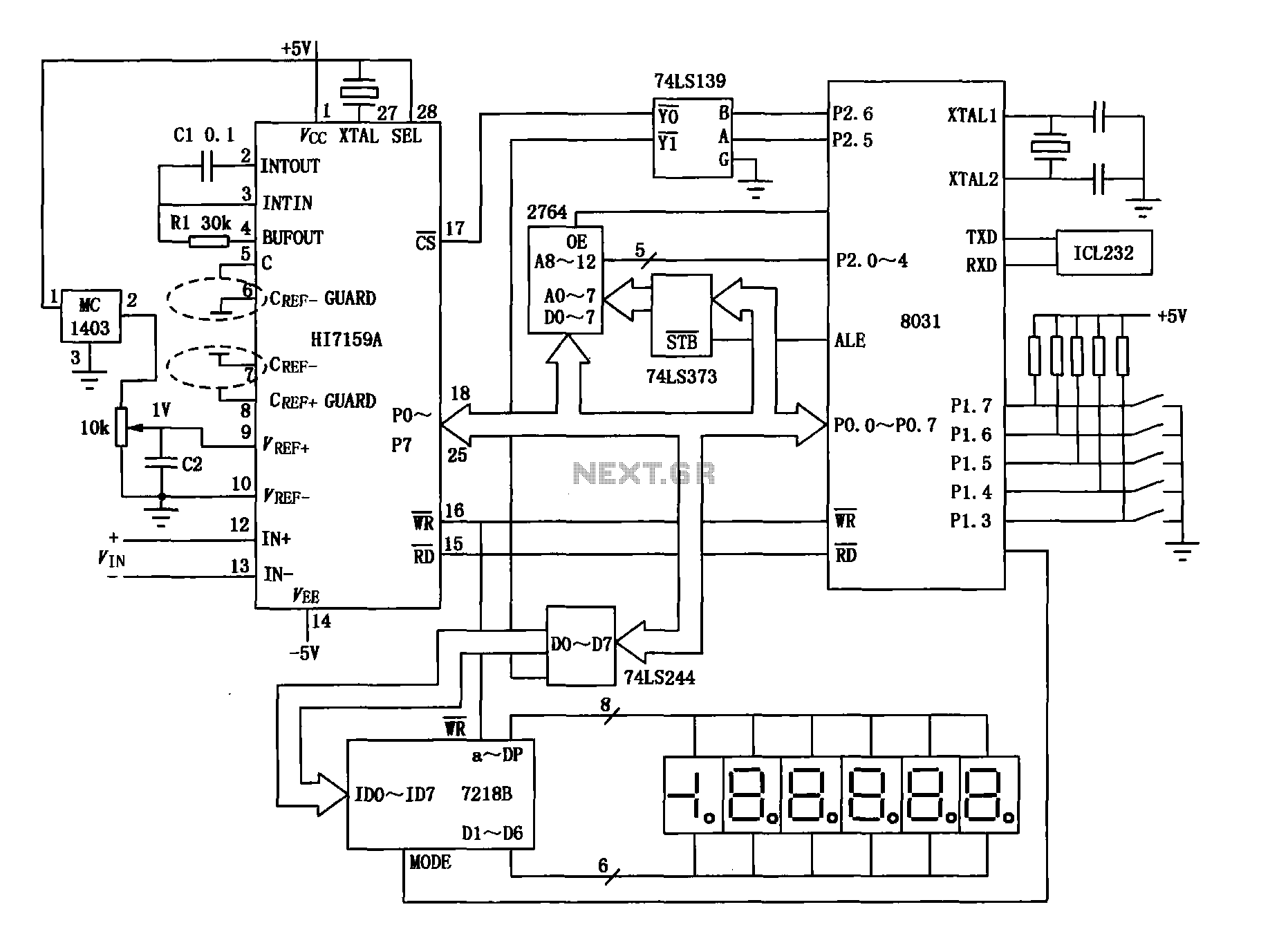
An intelligent digital voltmeter circuit utilizing the HI7159A, 8031 microcontroller, and various other components as illustrated in the figure. The internal circuit incorporates a successive cumulative integrator, digital zero function, low noise BIMOS technology, and other advanced features. In...
A resistance temperature sensor (RTD, resistive temperature device) is available in two types: NTC (negative temperature coefficient) and PTC (positive temperature coefficient). Resistance Temperature Detectors (RTDs) are essential components in temperature measurement systems. They operate on the principle that the...