
RF Induction Meter

The instrument is designed to measure inductance across a broad range, from 0.1 microhenry to 3 millihenries, by implementing a four-range switch that allows users to select the desired measurement range. The power supply consists of eight AA batteries, providing a stable 12-volt operation, which is essential for consistent measurement accuracy.
The core of the measurement technique involves a fixed frequency source, operating at four distinct frequencies, which enhances the versatility of the instrument. By resonating the unknown inductor with a variable capacitor, the circuit forms a parallel tuned circuit. This configuration is advantageous as it allows for precise tuning to achieve resonance, indicated by a dip in the current measured by the attached meter.
The calibration of the variable capacitor's dial in terms of inductance provides a user-friendly interface, allowing for straightforward readings. The design addresses potential inaccuracies that could arise from differing resistance components of the inductors by focusing on resonating the inductor rather than relying on a bridge configuration. This approach minimizes the impact of quality factor variations, particularly for low-Q inductors, ensuring that the measurements remain reliable across the entire range.
The schematic implementation is likely based on a Colpitts oscillator design, which is known for its stability and frequency precision, further enhancing the reliability of the inductance measurements. The overall design caters to both amateur and professional applications, providing a robust tool for inductance measurement in various electronic projects.This instrument measures inductances from 0. 1 microhenry to 3 millihenries divided into four ranges set by a switch. It operates from 12 volts, and is powered by eight AA type cells attached to the unit. I initially referred to Drew Diamond`s unit in Amateur Radio, November 1992 to see if it fitted my needs. Drew used a fixed crystal oscillator at around 3. 5 MHz to source a bridge where he compared the unknown inductor against a known 5 uH inductor. The bridge was balanced by adjusting a potentiometer which had its scale calibrated in terms of inductance. The meter measured a range of 0. 5 to 20 uH. I needed a wider inductance range than this. Also, I was a bit concerned that no provision had been made in Drew`s circuit to balance out the resistance components of the reference and unknown inductors.
If the two resistance components were largely different, and particularly if one of them (the unknown) was fairly low in Q, the dip shown in the balance meter would occur with the potentiometer reading offset from the calibration. I guess I could have modified the bridge to include resistance balance but I decided to operate my circuit in a different way.
I have used a fixed frequency source as in Drew`s circuit but extended this to four frequencies to expand the inductance range. Instead of using the bridge, the unknown inductor is resonated by adjusting a variable capacitor in parallel with the inductor.
The parallel tuned circuit is energised from the oscillator source via a meter which monitors the current into the circuit. The system is illustrated in Fig 1. Resonance is indicated by a dip in current as shown on the meter. A dial attached to the variable capacitor is calibrated in terms of inductance. Influenced by Drew`s crystal controlled, Colpitts type oscillator circuit, I wired up the circuit and proceeded to search through my box of cryst
🔗 External reference
Related Circuits
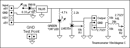
The circuit consists of two parts: The LM335 and its adjustment. The output of the LM335 is 10 millivolts per degree C, with 25 degrees C corresponding to 2.982 VDC. A reference circuit provides a zero reference voltage. It...
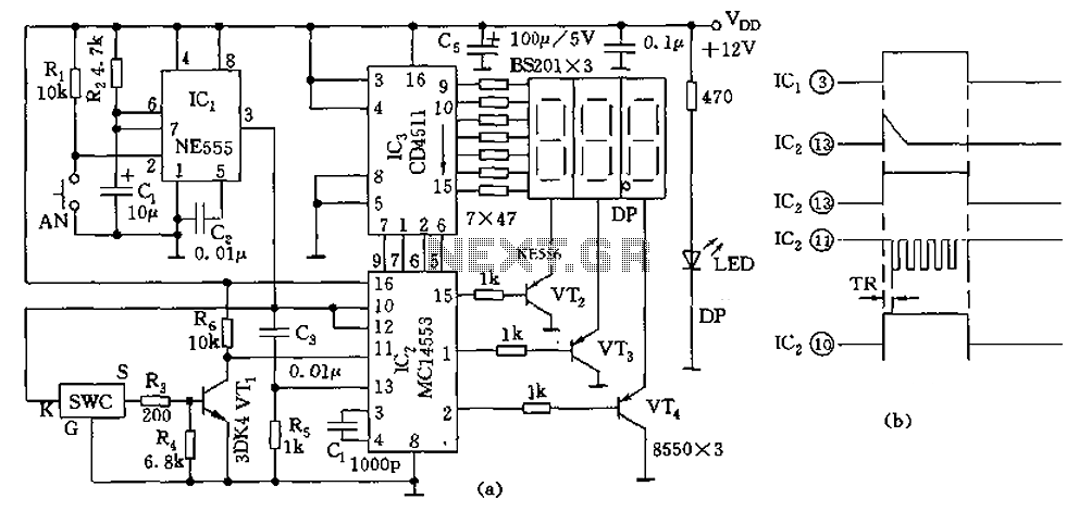
The digital thermometer consists of a temperature sensor, a single stabilizing circuit, a counter circuit, a decoding section, a driving circuit, and LED digital tubes among other components. It operates within a temperature range of 0 to 50 degrees...
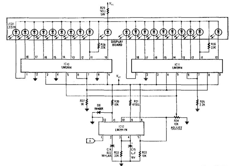
The analog display includes a frequency-to-voltage converter (IC12) along with bar-graph segment drivers IC10 and IC11. The calibration adjustment resistor R34 is configured to ensure that an engine RPM of 5,000 to 7,000 activates the first LED, which indicates...

A digital tachometer and speedometer utilizing a seven-segment display was initially attempted but not successfully implemented due to overcrowding of integrated circuits (ICs) and components. An LED tachometer was successfully constructed later, followed by the development of an LED...
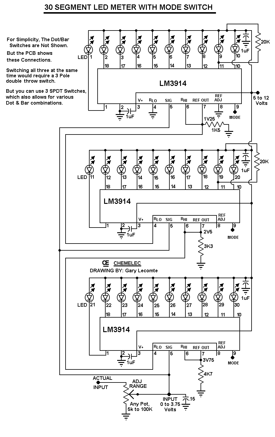
The circuit can be easily configured for full-scale voltages of either 20 or 200 volts by utilizing a suitable potentiometer on the input. It is critical not to exceed 30 volts at pin 5 of the LM3914. A 20...
Microcontroller-Based Accelerometer Project. Just as a speedometer is a device that measures speed, an accelerometer is a device that measures acceleration. The microcontroller-based accelerometer project utilizes an accelerometer sensor to detect changes in velocity and orientation. This project typically involves...