
ancient baudot teletype interface

The described circuit functions as a digital interface between a teletypewriter and a microprocessor, specifically designed to facilitate communication without the need for extensive software programming. The core components include a shift register, control logic, and a clock generator, which together streamline the process of sending data from the microprocessor to the teletypewriter.
The shift register receives parallel data in Baudot code, which is then converted to a serial format suitable for transmission. The synchronization is achieved through the microprocessor's READY line, allowing the teletypewriter to process incoming data seamlessly. The BUSY flip-flop is essential for managing the timing of data transmission; it activates when a START pulse is detected, indicating that data is ready to be sent.
As the data is loaded into the shift register on the next clock pulse, the cycle counter increments, ensuring that each bit is sent in the correct sequence. Once the cycle counter reaches 8, indicating that a full character has been transmitted, the BUSY and ENABLE flip-flops are reset, allowing the microprocessor to continue its operations without delay.
The circuit is designed to accommodate the specific timing requirements of the Model 28 Teletype, which necessitates that the STOP signal be applied for a duration 1.5 times longer than other signals. This is managed by the timing of the BUSY flip-flop's reset, which occurs on the falling edge of the clock signal when bit A is present at the output of the shift register.
The clock signal, which is critical for the operation of the circuit, is generated by a free-running IC timer, operating at approximately 75 Hz for the 10 character-per-second teletypewriter. For applications requiring different character rates, the clock frequency can be adjusted accordingly. The circuit exemplifies a practical solution for interfacing legacy teletypewriters with early microprocessor technology, showcasing ingenuity in overcoming the limitations of the era.
Corrections noted in the schematic include adjustments to the RC network of the 555 timer and the labeling of the INHIBIT input, ensuring accurate representation of the circuit's operation. Overall, this interface circuit represents a significant step in the evolution of microprocessor communication with peripheral devices, paving the way for future advancements in digital interfacing technology.This was my first published article, and fell out of my work on the homebrew 8008 system that is now in the Computer History Museum (that link includes four detailed photos). It`s basically a one-way simple UAR/T, though those devices were pricey back then and the design induces the host micro to wait while a character is sent (an interrupt wou
ld be better, of course, but my primitive software wasn`t doing anything else at the time). Of course, now one would eschew expensive external hardware and just use a port bit, but this was 1974 and static RAM locations were a scarce resource. This article had the effect of kindling the crazy notion of writing about my projects, and that became a career.
I was 22 at the time, living in an apartment in Kentucky, doing all I could to escape employment. A photo of my living room, including the machine and the amazing Model 28 teletype, is below the article. The lengthy software service routine generally required to interface a teletypewriter and an IC microprocessor, such as the Intel 8008, can be eliminated by the circuit shown here.
A shift register and some control logic are all that it takes, bringing total component cost to only about $6. 50. In the 8008 system, synchronization with the central processing unit is accomplished through this microprocessor`s READY line, making modification of the teletypewriter itself unnecessary.
The hardware configuration given in the figure is designed for a 10 character-per-second Model 28 Teletype, which uses the five-level Baudot code. If the intended application will not easily accommodate data storage in the Baudot code, conversion may be accomplished with a read-only memory, such as National`s MM5221TM.
(A Model 33 Teletype presents no decoding problem. ) During the time that the input parallel data is valid, the circuit receives the START pulse, which sets the BUSY flip-flop and takes the READY line low. The BUSY flip-flop also removes the reset from the cycle counter and enables the LOAD flip-flop, which is set on the next clock pulse.
This action loads the data at the input to the shift register and increments the cycle counter once. On the succeeding clock pulse, the ENABLE flip-flop is set, and the data in the register begins to shift to the right. For each shift pulse, the cycle counter is incremented by one until it reaches a binary count of 8. Then, the BUSY and ENABLE flip-flops are both reset, and the READY signal is restored to the microprocessor so that the central-processing unit can resume operation.
In the data character presented to the shift register, bit H, which is constantly held low, corresponds to the teletypewriter START pulse. Similarly, the register`s A and B bits are tied high, corresponding to the teletypewriter STOP pulse.
Since the STOP signal must be applied to the teletypewriter for approximately 1. 5 times longer than the other pulses, the BUSY flip-flop is reset on the falling edge of the clock, during the time that bit A is present at the register`s QH output. The serial output of the register switches the 60-milliampere teletypewriter current loop through the transistor.
The clock signal for the circuit is derived from the IC timer that is free-running at approximately 75 hertz. For teletypewriters that operate at 6 characters per second, the clock frequency should be about 45. 5 Hz. Software bypass. Digital Interface circuit provides synchronization between a teletypewriter and a microprocessor chip through the latter device`s READY line.
Normally, a long software routine is needed to make the interface. The input data is in the parallel Baudot code, and the output is for a 10 character-per-second teletypewriter. A free-running IC timer is used to produce the clock signal. Note two corrections in this schematic relative to the full-page image at the top of the article: +5 at the top of the RC network of the 555 timer, and INHIBIT input instead of
🔗 External reference
Related Circuits
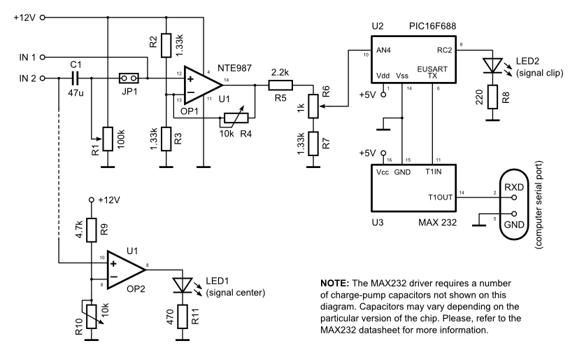
The data logger comprises a basic operational amplifier (op-amp) circuit that amplifies the input signal and transmits it to a PIC16F688 microcontroller for digitization, serialization, and subsequent transmission to a computer's serial port through a MAX232 serial driver. Some...

This setup enables the allocation of pins on an mbed for a specified interface without the need to recompile the code. It utilizes a PS/2 keyboard as an input device and an LCD as an output device. The system...
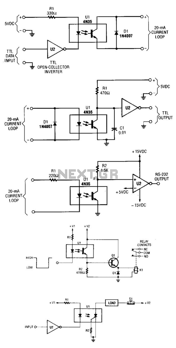
A circuit for isolating a variable resistor is presented. An optoisolator, which consists of an LED and a photo-conductive cell (or photoresistor), is utilized. The current flowing through the LED regulates its brightness, which subsequently dictates the resistance between...
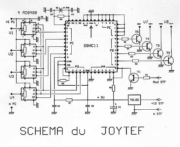
Using the software during flight simulation models of planes: REAL-FLIGHT, we first chose a housing of any transmitter empty direct connection potentiometers innings. However, this is not good because, first races of the potentiometers are only 90 degrees, which...
This is an interface circuit for digital data input. The circuit consists of a touch button, an operational amplifier (op-amp), a diode, a capacitor, and resistors. Any conductive surface can be used. The interface circuit designed for digital data input...
74hc573 is used to store data so that the previous content on SS is not vanish when we disable LE pin. T0 select the proper latch 74hc238, 3x8 decoder is used. And to convert BCD into decimal, 74ls48 converter...