
Antenna ground loop Isolator

You can simply make such a 1:1 transformer:
Take two strands of insulated wire, length: 10-20 cm. Twist the two wires, about 1-2 twists per cm is enough. Next, you need a small transformer core suitable for UHF frequencies. A donut-shaped ferrite core is recommended. Wrap the twisted wire a few turns around the core. One wire is the primary winding, the other the secondary (so it helps to color code the wires). Make the leads between the coaxial antenna plugs and the core as short as possible. You're making a transformer; if you have a red and a blue wire, connect the blue ends to one antenna plug, and the red wire to the other plug - not two colors on one plug. For TV transmission high-frequency signals, such a simple transformer (using a suitable core) is almost perfect. Do not try to use other types of transformers because your circuit would not work then and they would cause annoying interference to other TVs connected to the same antenna network (and in the worst case, you get cable TV people hunting for you because you messed with their cable network).
There is mention of a transformer circuit posted in the Usenet newsgroups. An article by Kari Hautanen discussed building a suitable transformer using the following method: Primary and secondary are three turns of 0.2 mm Cu-wire wrapped around a small magenta colored toroidal ferrite core. Although this method seems simple, the article did not specify the exact core size. One disadvantage of this circuit is that it breaks the continuous shielding of the antenna cable, which may make the antenna cable more susceptible to radio interference (for example, interference picked up by the ground loop itself). Usually, this is not a significant problem, but if severe interference is noticed, it may be necessary to stop using this isolator. The best place to install this isolator (to minimize the possibility of interference) is just between the TV receiver and the antenna cable leading to the wall.
A capacitor isolator scheme may seem unusual at first glance, but it effectively cuts the ground loop by providing high impedance to low frequencies (50 or 60 Hz mains frequency) while maintaining low impedance at the RF frequencies used for cable TV channels. This capacitor isolator approach has been a traditional technique in the TV industry. Older TVs, which had their chassis at mains potential, utilized this kind of approach to ensure that dangerous voltage could not reach the cable from the TV while allowing RF signals to pass through effectively. An isolator used in one old TV consisted of a 330 pF 500 VAC capacitor connecting the center of the coaxial cable to the tuner, while the shield of the coaxial cable was connected to the TV chassis through a high-voltage feedthrough capacitor (value unknown).A ground loop in your AV system caused by antenna connection or TV cable is very common if you have your computer connected to the same system. This type of ground loop problem can be solved by using suitable isolation between your AV system and the antenna cable.
The simplest way to get rid of the hum is to disconnect the antenna cable from the AV system. If you still want to watch cabe TV or listen to your radio an keep the system hum free then you have to install isolators to all those antenna cable connections your system has. Best solution to antenna/cable caused ground loop is to add a 1:1 transformer in the antenna signal, floating the VCR with respect to the cable tv ground. This solved the hum, no need for a messing with the audio signal, and the tv image quality did not suffer (most tv's get an overdose of signal from the cable tv anyway).
You can simply make such a 1:1 transformer: Take two strands of insulated wire, length: 10-20 cm. Twist the two wires, about 1-2 twists per cm is enough. Next you need a small transformer core suitable for UHF frequencies. I used a donut shaped ferrite core. Try looking in an old TV or radio. Wrap the twisted wire a few turns around the core. One wire is the primary winding, the other the secondary (so it helps to color code the wires). Make the leads between the coaxial antenna plugs and the core as short as possible. You're making a transformer, i.e. if you have a red and a blue wire: connect the blue ends to one antenna plug, and the red wire to the other plug - not two colors on 1 plug. For TV transmission high frequency signals such a simple transformer (using a suitable core) is almost perfect.
Do not try to use other types of transformers because your circuit would not work then and they would cause annoying interference to other TVs connected to same antenna network (and in worst case you get cable TV people hunting for you because you messed with their cable network). I have seen other transformer circuits posted in the Usenet newsgroups. Kari Hautanen wrote an article to sfnet.harrastus.elektroniikka newsgroup about antenna isolator. The article says that you can built a suitable transformer using following method: Primary and secondary are three turns of 0.2 mm Cu-wire wrapped around small magenta colored toroidal ferrite core.
Seems quite simple, but the article did not mention the exact core size. There is one disadvantage of this the circuit breaks the continuous shielding of the antenna cable which makes you antenna cable pick up radio interference more easily (for example radio interference picked by ground loop itself). Usually this is no big problem, but if you notice severe interference then you might have to stop using this isolator.
The beast place to put this isolator (to keep possibility of interference minimum) is just between TV receiver and antenna cable going to wall. This capacitor isolator scheme might feel quite strange at the first sight, but it actually works and cuts the ground loop because it provides high impedance to low frequencies (50 or 60 Hz mains frequency) but has low impedance at the RF frequencies that are used at cable for TV channels.
Capacitor isolator approach is an old trick used in TV industry. When the old TVs had their chassis at mains potential, they used this kind of approach to make sure that the dangerous voltage can get to the cable from the TV but the RF signal goes nicely to TV. Isolator used in one old TV had 330 pF 500 VAC capacitor which connects the center of the coaxial cable to tuner and the shield of the coaxial cable was connected to TV chassis through high voltage feedthrough capacitor (value unknown).
🔗 External reference
Related Circuits
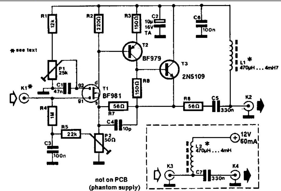
A whip antenna measuring between 30 to 50 cm is capable of receiving signals from 10 MHz to over 220 MHz. The circuit incorporates a BF981 dual-gate MOSFET (T1), which offers low noise characteristics, high input impedance, and enhanced performance. The...
The diameter of the antenna elements can range from 5.8 mm, while the dipole diameter can vary from 8 mm to 12 mm, with 12 mm being the recommended size. This adjustment can be made without altering the length...
An AM loop antenna is one of the true marvels of electronics. Requiring no power, it takes advantage of the resonant properties of an inductor and a capacitor connected in parallel to receive weak AM stations. The "loop" part...
This HD TV UHF wideband amplifier (Ultra High Frequency amplifier) provides a total gain of 10 to 15 dB within the frequency range of 400 to 850 MHz, making it suitable for areas with weak television signals. To ensure...
A phase-locked loop (PLL) is a servo system, or a feedback loop that operates with frequencies and phases. PLLs are known to be quite useful in communication systems, where they can extract small signals from significant noise. This discussion...
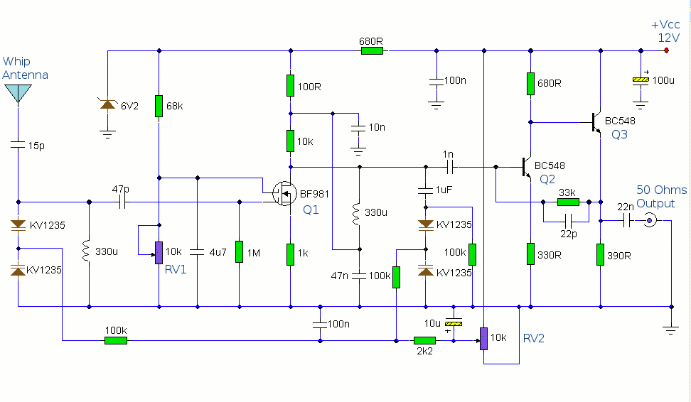
This circuit is designed to amplify the input from a telescopic whip antenna. The preamplifier is designed to cover the medium waveband from about 550KHz to 1650KHz. The tuning voltage is supplied via RV2, a 10k potentiometer connected to...