
AM LOOP ANTENNAS

An AM loop antenna operates based on electromagnetic induction and resonance principles. The antenna consists of a conductive loop, typically made from copper wire, which serves as the inductor. The size of the loop influences the inductance, while the tuning capacitor, connected in parallel, allows for frequency adjustment. This parallel LC circuit forms a resonant circuit that can be tuned to specific frequencies, enabling the antenna to effectively capture AM radio signals.
The loop's physical dimensions are critical; a larger loop can capture lower frequencies more effectively, while a smaller loop is better suited for higher frequencies. The quality factor (Q) of the loop antenna is important as it determines the selectivity and bandwidth of the signals received. A higher Q indicates a narrower bandwidth, which can improve reception of a specific station but may limit the ability to receive adjacent channels.
To optimize performance, considerations such as the loop's orientation, proximity to obstructions, and the presence of nearby conductive materials should be taken into account. The antenna should ideally be positioned in an open area to minimize interference and maximize signal strength.
Overall, the AM loop antenna exemplifies a simple yet effective design that leverages fundamental electrical principles to achieve reliable radio reception without the need for external power sources.An AM loop antenna is one of the true marvels of electronics. Requiring no power, it takes advantage of the resonant properties of an inductor and a capacitor connected in parallel to receive weak AM stations. The "loop" part of the antenna is the inductor, and the tuning capacitor makes it resonate at a desired frequency.
As a boy in Abilene in 1967, I discovered the basic principle of the loop antenna. By removing a relatively small spiral loop in my five tube table radio, and substituting a much larger loop salvaged from an older radio, I could receive my favorite statio 🔗 External reference
Related Circuits
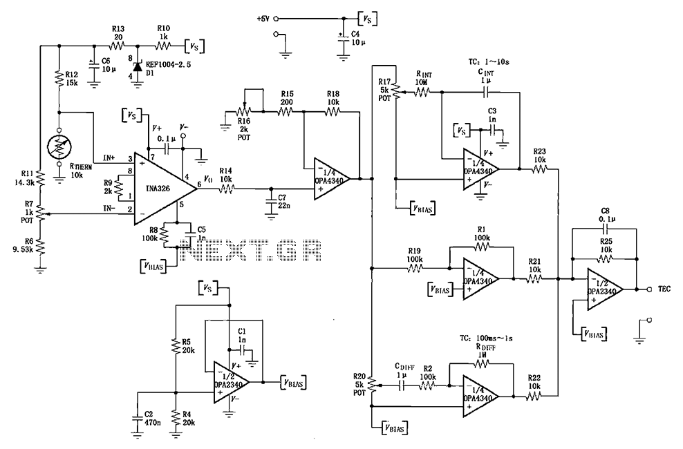
The INA326/327 forms a single power PID (proportional-integral-derivative) controller as illustrated in the temperature control loop. This circuit is primarily designed for temperature measurement and control. A thermistor, designated as RTHERM, detects temperature changes and converts them into an...

Design a low-cost 4- to 20-mA receiver circuit for control loops using an analog-to-digital converter (ADC). The design of a low-cost 4- to 20-mA receiver circuit is essential in industrial applications for monitoring and controlling processes. This current loop standard...

Wound on a 3 foot length of PVC pipe, the long loopstick antenna was an experiment to try to improve AM radio reception without using a long wire or ground. It works fairly well and greatly improved reception of...
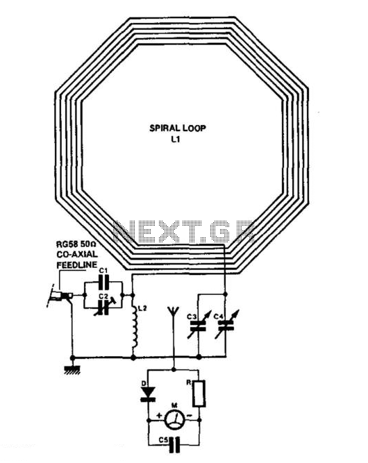
C1 = 3750 pF 500 V silver-mica capacitor. C2 = 100 pF preset capacitor (Jackson C803). C3 = 75 pF variable capacitor (Jackson C809) with a knob. C4 = 12.7 pF variable capacitor (Jackson C16) with a knob. C5...
Continued from the previous post. The same principle is true for the following: temperature to current transmitter. In this case, the input voltage is proportional to the measured temperature, not the rotation. The temperature input is a full analog,...
The loop can be any type of hookup wire, with a maximum resistance of about 90K. Using very thin wire (40AWG, for example) will create a highly sensitive trip wire, but will reduce the distance it can be strung...