
Antenna tunning circuit for 27MHz CB band

The antenna tuning circuit described is designed to optimize the performance of 1/2 wave length antennas, specifically for use with Citizen Band (CB) transceivers that typically operate at an input resistance of 50 Ohms. The circuit incorporates three capacitors: C1, which is utilized for fine tuning; C2, which serves as the primary tuning capacitor; and C3, which is adjusted in conjunction with C2 to achieve a standing wave ratio (SWR) of 1:1, indicating a perfect match between the antenna and the transceiver.
The inductor, labeled L, consists of 11 turns of insulated copper wire with a diameter of 1mm, forming a coil that plays a crucial role in the tuning process by providing the necessary inductance to match the impedance of the antenna system. The configuration of the coil and the capacitors allows for the adjustment of the resonant frequency of the circuit, enabling it to accommodate varying lengths of antennas beyond the standard 1/2 wave length.
When using a 1/2 wave length antenna, which measures approximately 5.5 meters, it is essential to set C3 to its maximum capacitance to ensure optimal performance. The circuit can interface with the receiver via either an SO-239 connector, which is a UHF type commonly used in RF applications, or through BNC connectors, providing versatility in connection options. To minimize signal loss and maintain signal integrity, it is recommended to keep the cable length between the transceiver and the tuning circuit as short as possible. This design ensures efficient transmission and reception of signals, making it suitable for CB communication applications.The antenna tunning circuit can accommodate 1/2 wave length antennas or higher, for input resistances of 50 Ohms which make it suitable for CB (Citizen Band) transceivers. C1 is for fine tunning and C2 is just for tunning. Turning C3 with the help of C2 you can set the SWR to 1:1. The Coil L is made of 11 turns of insulated copper wire with diameter of 1mm. If you use 1/2 wave length antenna (5.5m) then C3 has to be set to highest capacitance. The connection with the receiver can be done using the SO-239 connector (UHF) or with BNC's. Keep the distance of the cable between the transceiver and the tunning cir
Related Circuits
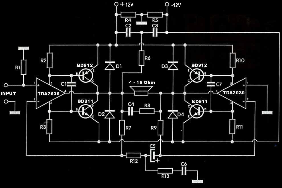
The TDA2030 amplifier circuit is suitable for driving low-frequency subwoofer speakers in home theater systems. The TDA2030 is a monolithic integrated circuit designed for use as a low-frequency class AB amplifier. This TDA2030 amplifier design requires a dual power...
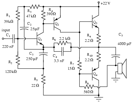
Note that Q3 and Q4 in the figure below are complementary, with Q3 being an NPN transistor and Q4 being a PNP transistor. This circuit is suitable for moderate power audio amplifiers. For a detailed explanation of this circuit,...
This is an intercom circuit that utilizes the LM380 as the audio amplifier and two transistors for the microphone preamplifier. The sound quality is sufficiently good while maintaining a low construction cost. The circuit comprises two identical intercom units,...

This is the design circuit diagram of an ultrasonic mosquito repeller. The circuit operates based on the theory that insects, such as mosquitoes, can be repelled by sound frequencies in the ultrasonic range (above 20 kHz). The circuit utilizes...
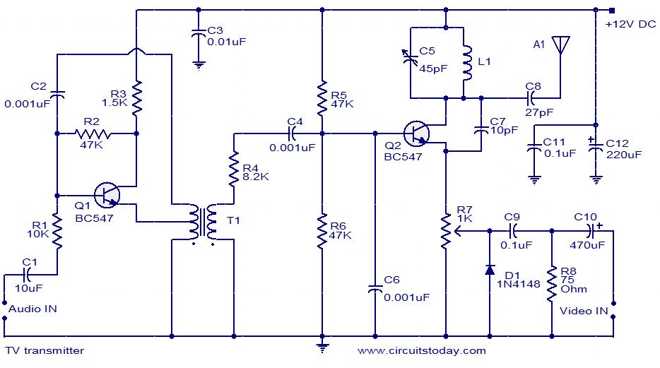
A simple two-transistor TV transmitter circuit that operates from 12V. It is compatible with PAL B and PAL G systems. The described circuit utilizes two transistors to create a basic television transmission system capable of operating on a 12V power...
Can simulate the character Mu symbol. A bone dish SET code is needed that effectively manages the decimal point. An inverted J is required to open its mouth. Left foot circuit diagram. The project involves designing a circuit that simulates...