
Arduino Audio Output

To create a digital-to-analog converter (DAC) using an Arduino, one can utilize the Pulse Width Modulation (PWM) feature available on many Arduino boards. PWM allows the microcontroller to simulate an analog output by varying the duty cycle of a digital signal. This method is particularly useful for generating audio signals or controlling the brightness of LEDs.
The basic setup involves connecting a low-pass filter to the PWM output pin of the Arduino. The filter, typically composed of a resistor and capacitor, smooths the PWM signal into a more stable analog voltage. The resistor (R) and capacitor (C) values can be selected based on the desired cutoff frequency, which determines how effectively the PWM signal is filtered. A common configuration might use a resistor of 1k ohm and a capacitor of 10µF, resulting in a cutoff frequency of approximately 15.9 Hz.
To implement this, the Arduino can be programmed to output a PWM signal using the `analogWrite()` function. This function takes two parameters: the pin number and the value (ranging from 0 to 255) that corresponds to the desired voltage level. For example, a value of 127 would yield approximately half of the supply voltage, while a value of 255 would output the maximum voltage.
In addition to audio applications, this DAC setup can also be employed for various control tasks, such as adjusting the speed of motors or the brightness of lights. By modifying the duty cycle of the PWM signal, the output voltage can be finely tuned to meet the requirements of the specific application.
Overall, this basic DAC configuration using an Arduino provides a simple yet effective means of generating analog voltages from digital signals, expanding the versatility of the microcontroller in various electronic projects.Generate sound or output analog voltages with an Arduino. This Instructable will show you how to set up a really basic digital to analog converter so.. 🔗 External reference
Related Circuits
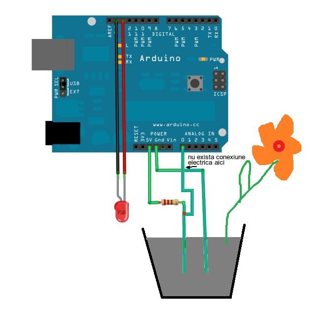
This is a simple Arduino project for a soil moisture sensor that will light up an LED at a certain moisture level. It uses the Arduino Duemilanove microcontroller. This project employs a soil moisture sensor to monitor the moisture content...
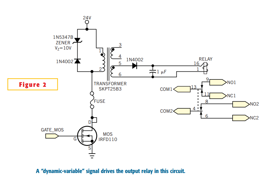
Many electronic-control systems have digital outputs that use transistors. One method of improving the security in these outputs is to use an oscillating signal to represent a logic-high state instead of a fixed voltage level. This type of signal,...
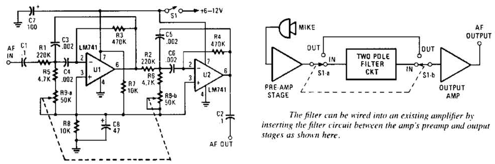
This variable-frequency audio bandpass filter is constructed using two 741 operational amplifiers connected in cascade. The two 741 op amps are configured as identical RC active filters and are cascaded to enhance selectivity. The filter's tuning range spans from...
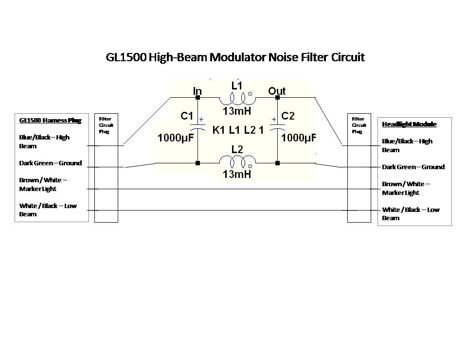
A power filter is a device that is placed before devices such as GPS, MP3 players, or radar detectors connected to the auxiliary circuit. When properly used and installed, these filters can eliminate modulator noise from any system. Observing...
This circuit is a 20W Audio Amplifier kit, based on the TDA2005 IC, a class B dual audio amplifier, specifically designed for car radio applications etc. Power supply - 18 VDC. Output power - 20 W, 4 ?. IC...

This is a circuit for an audio frequency meter. This circuit utilizes a 555 IC configured as a monostable multivibrator (one-shot trigger). A monostable multivibrator can function as a frequency-to-voltage converter by producing a fixed pulse width, with the...