
Arduino based camera trigger circuit

The momentary push buttons, identified as "switch A" and "switch B," are connected to the microcontroller's digital inputs 2 and 3. These buttons serve as the primary user interface with the trigger unit, allowing users to toggle between different functional states. Although not illustrated in the circuit diagram, two BNC plugs are present to bypass these switches, enabling the use of a BNC cable with an attached switch for remote event triggering. The outputs from the microcontroller are utilized to power various LEDs and a small piezo-buzzer, which indicates the current state of the program. Digital outputs also energize the laser diodes, provide TTL logic signals, and control the cameras and radio transmitter through four optocouplers (4N25, Vishay Semiconductors).
Digital output 4, labeled "Stim-TTL," is designated for triggering the radio transmitter that communicates with the onboard stimulator chip. Depending on the position of switch S1, either a left (OUT1) or right (OUT2) button press on the transmitter is simulated. The connection to the transmitter is optocoupled (OK3 and OK4) to prevent interference from the high electrical noise present in the transmitter circuit. Digital output 5 connects to a buzzer that signals transitions between program modes with short beeps and produces a longer beep during trigger events. Digital output 6 is linked to an LED that indicates trigger events, while digital output 7 corresponds to an LED signaling idle status. Digital output 8 is associated with an LED indicating armed status. Digital output 10 supplies power for the low-power laser diodes (Laser1 and Laser2), both of which can operate on the 20 mA provided by the Arduino. Digital output 11 generates a 5 V TTL signal synchronized with the stimulus. Digital outputs 12 and 13 can be employed to control high-speed cameras, with both outputs being optocoupled to ensure electrical isolation from the cameras. Output 12 is timed to align with a trigger event, while output 13 is timed to coincide with the stimulus event occurring 84 ms later.
The design of this circuit effectively integrates various components to create a responsive and interactive system, suitable for applications requiring precise control over light sensing, triggering events, and user interface management. The use of optocouplers enhances the reliability of the system by mitigating the effects of electrical noise, ensuring that the signals remain clean and functional. The combination of analog inputs and digital outputs allows for versatile operation, making this circuit adaptable to a range of experimental and practical applications in electronics and automation.The heart of the circuit consists of the Arduino microprocessor which is indicated by the header pins on the left of the circuit schematic shown on the right (click to open in new window). Two of the analog inputs (0 and 1) are connected to the emitter sides of TEMT6000 ambient light sensors (Vishay Semiconductors, Shelton, CT), which act as laser targets.
When light shines on these sensors, current runs from collector to emitter, so that the analog inputs are close to 5 V. In darkness, no current flows across the transistors, and the 10 KOhm resistors pull the inputs to ground.
In a realistic situation, when an object blocks the laser beam impinging upon a sensor, the voltage will be somewhere in between 0 and 5 V, which gets encoded as a value between 0 and 1023 by the 10-bit analog converter. (The alignment routine described in section above helps find the correct threshold values.) The momentary push buttons labeled "switch A" and "switch B", and connected to the microcontroller's digital inputs number 2 and 3 (see circuit diagram) are the main user interface with the trigger unit. Pressing these buttons allows switching between the functional states described above. Not shown in the circuit diagram are two BNC plugs that bypass these switches, so that a BNC cable with an attached switch can be used to trigger events from a certain distance to the unit.
Outputs from the microcontroller The Arduino's outputs are used to power various LEDs as well as a small piezo-buzzer, indicating the current state of the program. Digital outputs also power the laser diodes, provides TTL logic signals, as well as switch the cameras and the radio transmitter via four optocouplers (4N25, Vishay Semiconductors, Shelton, CT).
The following is a more detailed list of the outputs depicted in the schematic circuit diagram. Digital output 4 (labeled "Stim-TTL") is used to trigger the radio transmitter that communicates with the on-board stimulator chip. Depending on the position of switch S1, either a left (OUT1) or right (OUT2) button press on the transmitter is emulated.
The connection to the transmitter is optocoupled (OK3 and OK4) to avoid contamination by the very high electrical noise present in the transmitter circuit. Digital output 5 is connected to a buzzer which indicates transitions between program modes with short beep sounds.
It also produces a longer beep when a trigger event occurs. Digital output 6 provides a signal to an LED indicating trigger events Digital output 7 is for the LED indicatingIdle status Digital output 8 is for the LED indicating Armed status Digital output 10 provides power for the low-power laser diodes (Laser1 and Laser2). Both lasers can be run on the 20 mA an Arduino can deliver. Digital output 11 provides a 5 V TTL signal timed to coincide with the stimulus. Digital outputs 12 and 13 can be used to switch the high speed cameras. Both outputs are optocoupled to electrically isolate the circuit from the cameras. Output 12 is timed to coincide with a trigger event, output 13 is timed to coincide with the stimulus event occuring 84 ms later.
🔗 External reference
Related Circuits

When the doorbell switch is pressed, two monostable stages are sequentially activated, applying bias to a pair of voltage-controlled resistor stages. These stages modulate the outputs from a pair of tone generators. The resulting signals are then fed to...
The motor switch control circuit depicted in the figure provides two speed settings for counter-steering, allowing for operation at two speeds in opposite directions. The motor switch control circuit is designed to facilitate the operation of a motor at two...

The cause may be dry solder joints, defective LEDs, or a flat battery (possibly due to a stuck key). The human eye cannot perceive infrared light, while a standard phototransistor such as the BP103 operates effectively in the infrared...
White LEDs have a rated current at a voltage drop of about 3.3 to 3.4 V. It is ideal to be powered from the battery voltage which is slightly larger. Then there is the best energy used. In this...
This circuit diagram illustrates a setup for two flashing LEDs designed for various applications, including model construction and recreational uses. It features adjustable flashing speeds controlled by two potentiometers. The circuit comprises a combination of active and passive components....
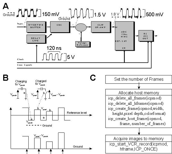
This document provides technical details regarding the hardware and software of a complete imaging system that utilizes a fast CCD sensor and a 41 Msample/s A/D converter. This system is capable of acquiring full-frame digitized images at a resolution...