
Atmega 8515 programming help

A parallel programmer for the ATmega8515 microcontroller can be constructed using a few essential components. The ATmega8515 is an 8-bit AVR microcontroller that supports the In-System Programming (ISP) method, which allows programming without removing the chip from the circuit.
To create a parallel programmer, a standard parallel port interface can be utilized, which connects to the microcontroller's programming pins. The programmer will require a suitable connector to interface with the ATmega8515, typically utilizing the MISO, MOSI, SCK, RESET, and VCC pins.
The programming process involves sending specific commands to the microcontroller, which can be accomplished using software tools designed for AVR programming. These tools often provide a user-friendly interface and support for various programming modes, including bootloader and ISP modes.
In terms of assembly instructions, the ATmega8515 instruction set comprises a variety of operations, including arithmetic, logic, control flow, and data manipulation commands. These instructions are executed directly by the microcontroller's CPU and can be used to develop efficient low-level applications. A comprehensive reference guide for the assembly language can be found in the ATmega8515 datasheet, detailing each instruction's syntax, functionality, and timing characteristics.
Overall, the combination of a parallel programmer and a thorough understanding of assembly instructions will enable effective programming and utilization of the ATmega8515 microcontroller in various electronic applications.i am going to programmer my atmeg8515 Mc and i am searching for good and easy parallel programmer for it also i want to know the assembly instructions .. 🔗 External reference
Related Circuits
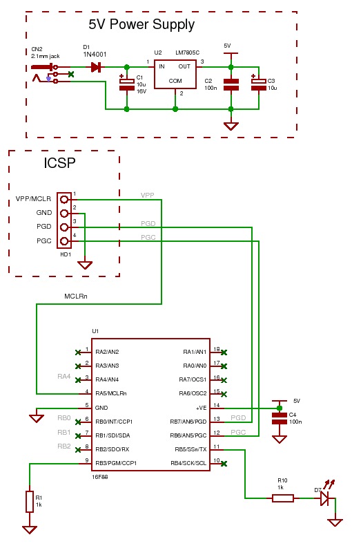
For the other components, most of the necessary items should be available if any type of electronics work has been done, except for the programmer, RS232 chip, and PIC. To transfer information from the project to the PC, a...
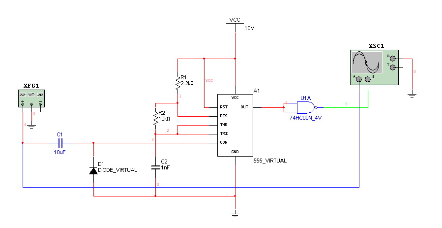
Hello everyone. I need some help. I have constructed a PWM and PPM circuit. The output is functioning smoothly, but I am experiencing some problems and I am not very experienced. The PWM (Pulse Width Modulation) and PPM (Pulse Position...
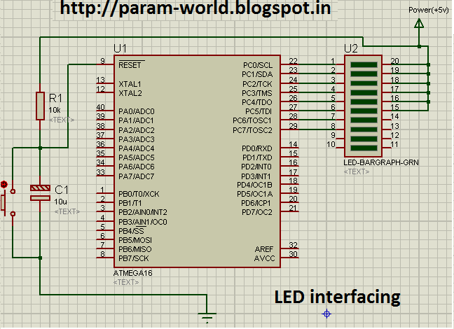
The circuit interfaces an LED with an AVR microcontroller (ATMega16). The components used include one ATMega16 microcontroller, a 10K resistor, a 16uF/25V capacitor, a push button switch, and a green LED bar instead of eight individual LEDs. The power...
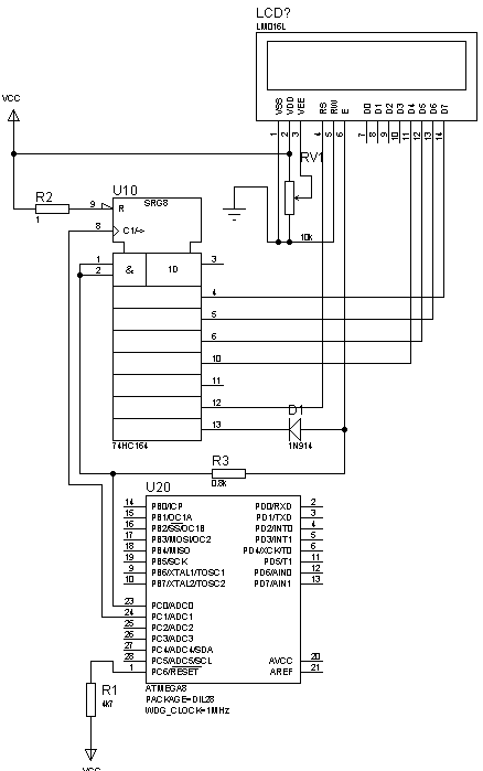
This is not a new idea for interfacing an LCD using two wires, but it can be beneficial in situations where there are insufficient microcontroller pins. This example is based on the Hitachi 44780 alphanumeric LCD. The provided circuit...
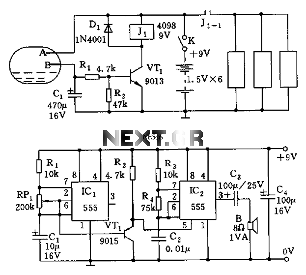
The call is triggered by the position sensing circuit, which activates the control circuit and SOS alarm circuit. This system is designed for critically ill patients or to assist disabled individuals in the event of a fall. A position...
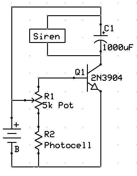
A new user has recently discovered a Laser Alarm System and has decided to explore this project. The Laser Alarm System is a security device that utilizes laser beams to detect unauthorized entry or movement within a designated area. The...