
Audio Booster
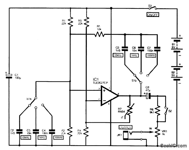
The design of the amplifier circuit focuses on achieving a gain of 20 dB, which indicates that the output signal will be 10 times the amplitude of the input signal. This gain is suitable for various applications, including audio signal amplification and sensor signal conditioning.
The choice of components is critical in defining the frequency response of the amplifier. Typically, resistors and capacitors are selected based on desired cutoff frequencies, which determine the bandwidth of the amplifier. For instance, using a capacitor in the feedback loop can create a high-pass filter effect, allowing signals above a certain frequency to pass while attenuating lower frequencies. Conversely, a capacitor placed at the input can create a low-pass filter, blocking high-frequency signals.
The construction on a veroboard allows for a straightforward assembly process, where components can be easily placed and soldered in a compact layout. This method also facilitates modifications and troubleshooting, as connections can be adjusted without the need for a custom printed circuit board (PCB).
Power supply considerations are also essential; the amplifier should be powered by a stable voltage source to ensure consistent performance. Bypass capacitors may be employed to filter out noise from the power supply, enhancing the overall signal integrity.
Overall, this small and portable amplifier unit is designed for versatility and ease of construction, making it an excellent choice for hobbyists and professionals alike looking to amplify low-level signals in a variety of applications.Small and portable unit, Can be built on a veroboard The amplifier s gain is nominally 20 dB. Its frequency response is determined primarily by the value.. 🔗 External reference
Related Circuits
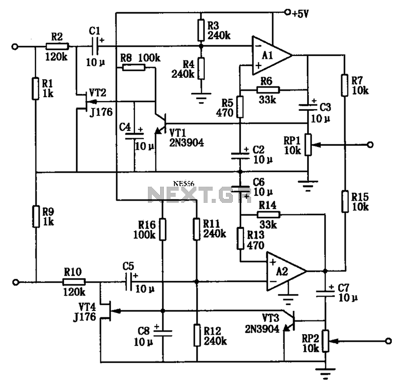
The Audio Automatic Gain Control (AGC) circuit monitors the output signal level of an audio preamplifier. When the input signal increases, the AGC circuit automatically reduces the amplifier's gain. Conversely, when the input signal decreases, the AGC circuit increases...
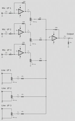
The microphone inputs are amplified approximately 100 times or 40 dB, with the total gain of the mixer, including the summing amplifier, reaching 46 dB. The microphone input is designed for microphones that produce an output of around 2...
High-quality modular design, powered by a 9V battery, with very low current consumption. The objective of this project was to design a small, portable mixer. The project focuses on creating a compact audio mixer that operates efficiently on a 9V...
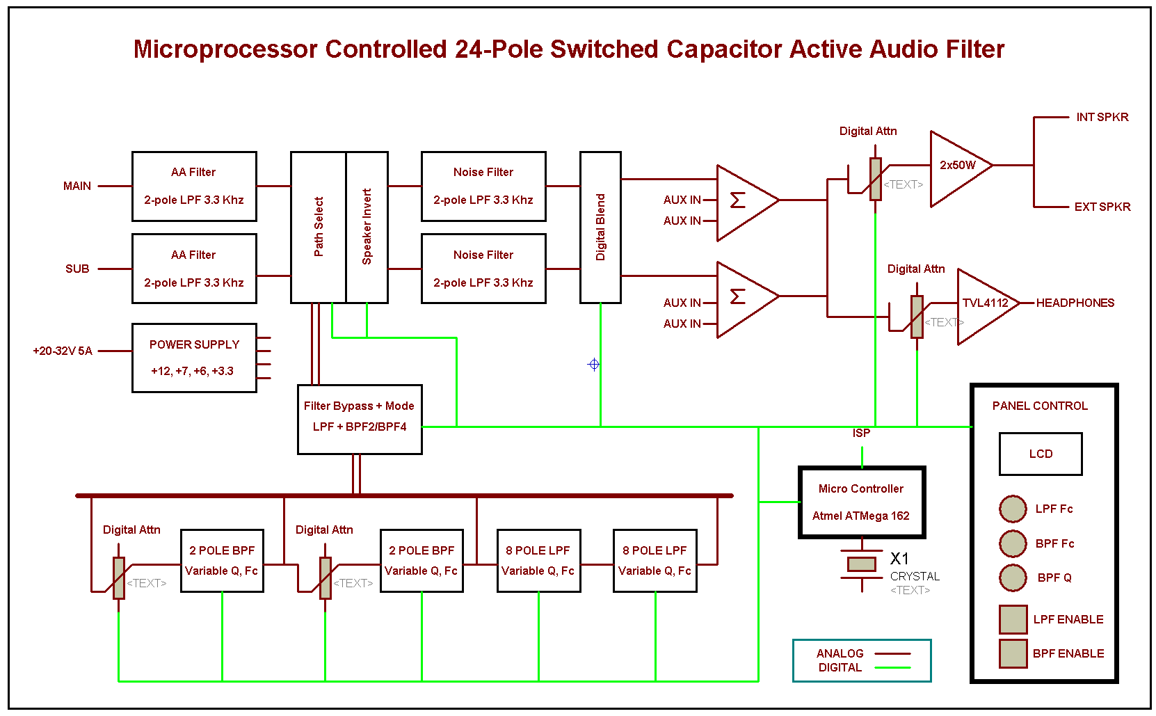
This project extends two previous projects: the first involves adding an active filter (APF) type high-Q bandpass feature to the second receiver of the FT-2000. The second aspect is inspired by childhood memories of active filters. An active audio...
The complete circuit diagram for the audio sine-wave generator is presented. Resistors R1 and R2 provide biasing to the non-inverting (pin 3) input of IC1, and their parallel resistance constitutes one component of the Wien network. They correspond to...
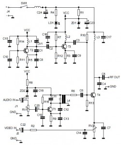
This is the circuit diagram of an audio/video modulator. The circuit converts audio and video signals into a UHF TV signal. It is designed to connect a video signal originating from a camera or other video source to a...
Warning: include(partials/cookie-banner.php): Failed to open stream: Permission denied in /var/www/html/nextgr/view-circuit.php on line 713
Warning: include(): Failed opening 'partials/cookie-banner.php' for inclusion (include_path='.:/usr/share/php') in /var/www/html/nextgr/view-circuit.php on line 713