
Audio interface for Telephone line

The described circuit effectively extracts audio signals from a telephone line while ensuring safety and compatibility with external equipment. The use of a transformer is critical for isolating the telephone line from the connected devices, which mitigates the risk of damage from voltage spikes or electrical interference.
The non-polarized capacitor, positioned in series with the transformer, plays a vital role in preventing direct current (DC) from flowing through the transformer winding. This is essential for maintaining the proper operational state of the telephone line, specifically allowing it to return to the on-hook state when not in use. The capacitor must be rated for voltages exceeding the combined peak ringing voltage of 90 volts and the on-hook voltage of 48 volts, leading to a recommended voltage rating of at least 400 volts to ensure reliability across varying local conditions.
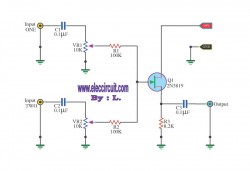
The audio output level from the transformer is approximately 100 millivolts, suitable for connection to high impedance inputs such as amplifiers or tape recorders. For signal amplification, a three-transistor amplifier circuit can be employed, enhancing the audio signal while maintaining fidelity.
To protect the circuit from overvoltage conditions, particularly during ringing signals, two diodes are connected in parallel across the transformer’s secondary winding. These diodes serve as clamping devices, limiting the audio signal to a maximum of 700 millivolts peak, which safeguards downstream components from excessive voltage levels. Common silicon diode types, such as 1N400X, 1N4148, or 1N914, can be utilized for this purpose.
Finally, a 620-ohm resistor is included in the circuit design to minimize the loading effect on the telephone line when interfacing with low impedance loads. This resistor ensures that the line remains operational without significant signal degradation, thus preserving the integrity of the audio signal during transmission. Overall, this circuit design provides a robust solution for audio extraction from telephone lines, balancing performance with safety considerations.Audio from a telephone line can be obtained using a transformer and capacitor to isolate the line from external equipment. A non-polarized capacitor is placed in series with the transformer line connection to prevent DC current from flowing in the transformer winding which may prevent the line from returning to the on-hook state.
The capacitor should have a voltage rating above the peak ring voltage of 90 volts plus the on-hook voltage of 48 volts, or 138 volts total. This was measured locally and may vary with location, a 400 volt or more rating is recommended. Audio level from the transformer is about 100 millivolts which can be connected to a high impedance amplifier or tape recorder input. The 3 transistor amplifier shown above can also be used. For overvoltage protection, two diodes are connected across the transformer secondary to limit the audio signal to 700 millivolts peak during the ringing signal.
The diodes can be most any silicon type (1N400X / 1N4148 / 1N914 or other). The 620 ohm resistor serves to reduce loading of the line if the output is connected to a very low impedance. 🔗 External reference
Related Circuits
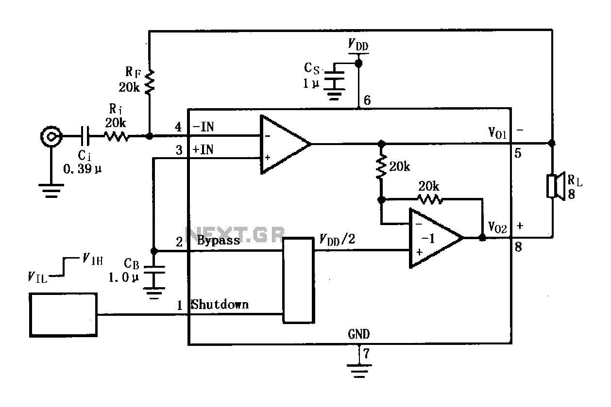
The LM4819 audio power amplifier is designed to amplify audio signals. An audio signal is input through the coupling capacitor (Ci) and the resistor (Ri) applied to the inverting input terminal (pin 3) of the amplifier. The inverting input...
This design is based on an 18 Watt audio amplifier and was developed primarily to meet the needs of users who are unable to find the TLE2141C chip. It utilizes the widely available NE5532 dual integrated circuit; however, its...
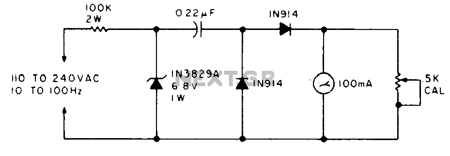
The meter will display the frequency from a power generator. Incoming sine waves are transformed into square waves by the 100K resistor and the 6.8 V zener diode. The square wave is differentiated by the capacitor, and the current...
Wind 6 turns of solid wire on a pen or pencil that is just under 1/2 inch in diameter. Remove the wire from the pencil and spread the winding to make a length of 3/4 inch. Solder C2 somewhere...
Below are three examples of controlling a relay from the PC's parallel printer port (LPT1 or LPT2). Figure A shows a solid-state relay controlled by one of the parallel port data lines (D0-D7) using a 300-ohm resistor and a...
This circuit is a simple mixer circuit that can mix two signal channels into one output channel. It utilizes a codec circuit to convert stereo audio into mono audio. Additionally, the circuit can increase the number of channels by...