
Audio-powered noise clipper

The circuit employs two transformers, T1 and T2, designed to match a high-impedance audio source to a lower impedance load. These transformers facilitate the conversion of audio signals, ensuring efficient power transfer and minimizing signal loss. The choice of transformers with an impedance ratio of 600 to 8 ohms allows for compatibility with various audio equipment, while the option to use transistor radio output transformers with 500 to 4 ohms offers flexibility in circuit design.
Transistors Q1 and Q2 serve as the primary active components responsible for signal processing. The 2N2222 NPN transistor (Q1) and the 2N2907 PNP transistor (Q2) are commonly used in audio applications due to their reliability and performance characteristics. In this configuration, Q1 is responsible for clipping the positive peaks of the audio signal, while Q2 handles the negative peaks. This clipping action is critical for preventing distortion and maintaining audio fidelity at higher signal levels.
The inclusion of diodes D1 and D2, specifically 1N270 signal diodes, plays a crucial role in isolating the clipping circuits. The diodes allow for unidirectional flow of current, ensuring that each transistor only engages in clipping its respective half of the audio waveform. This isolation not only protects the transistors from potential damage due to reverse current but also enhances the overall performance of the circuit by maintaining a clean separation between the positive and negative clipping processes.
The circuit also features a 2.5 kΩ potentiometer, which is used to set the threshold level for clipping. By adjusting this potentiometer, the user can establish the desired audio operating level, allowing for customization based on the specific requirements of the audio signal being processed. Once set, the potentiometer typically requires little to no further adjustment, providing a stable and reliable operation throughout the audio processing task.
Overall, this circuit design effectively combines transformers, transistors, and diodes to create a robust audio signal processing solution, capable of managing clipping while ensuring high-quality audio output.Tl and T2 are 600 to 8 ohm transformers (any transistor radio output transformers with 500 to 4 ohm impedance may be used). Ql is a 2N2222 npn transistor, and Q2 is a 2N2907 pnp transistor. Dl and D2 1N270 signal diodes (HEP 134 or 135). Two transistors, powered by the audio power contained within the signal, will clip signal peaks which exceed the threshold established by the 2.5 potentiometer.
The diodes isolate the positive and negative clipping circuits represented by the npn and pnp transistors, respectively. A desired audio operating level can be established and the potentiometer needs little or no further adjustment.
Related Circuits
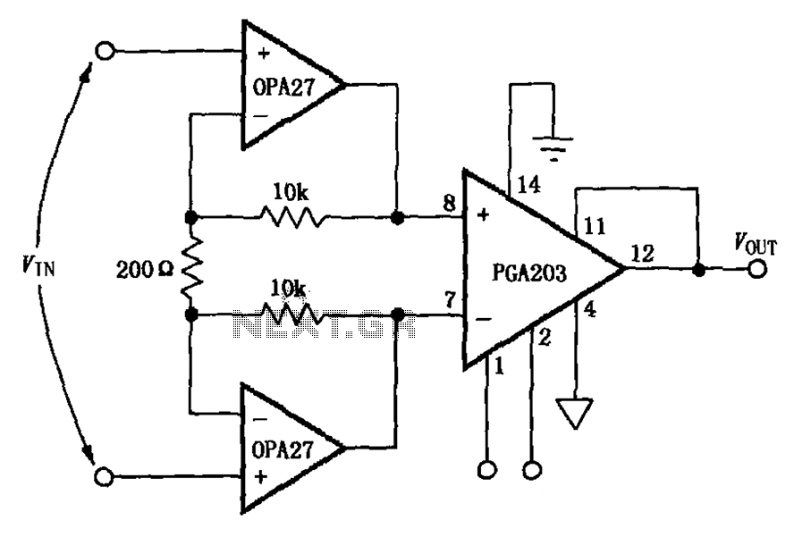
The circuit depicted in the figure features a PGA203 operational amplifier (op amp) and two OPA27 op amps, forming a low-noise differential amplifier. The input stage utilizes the PGA203 in conjunction with the two OPA27 op amps. The non-inverting...
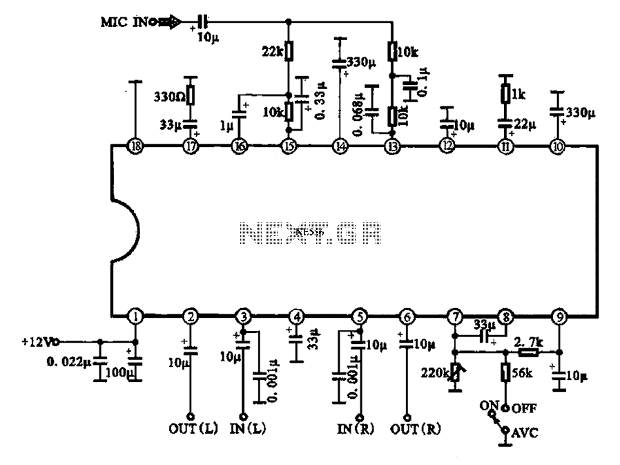
Automatic volume adjustment with ambient noise control circuit. In car stereos and similar devices, the ambient noise level varies during high-speed and low-speed driving or while stationary, leading to different volume requirements. A fixed volume adjustment method may negatively...
The MFOS Noise Toaster circuit comprises seven primary components: a voltage-controlled oscillator (VCO), a white noise generator, a voltage-controlled low-pass filter, a low-frequency oscillator (LFO), a simple attack-release (AR) envelope generator, a simple voltage-controlled amplifier (VCA), and a one-watt...
One LED monitors three levels: 50, 70 & 85 dB. Useful to detect too noisy environments. This circuit is intended to signal, through a flashing LED, the exceeding of a fixed threshold in room noise, chosen from three fixed...

This design circuit outlines a simple, low-cost, and ultra-compact VHF/UHF Low-Noise Amplifier (LNA) that can be implemented using the MAX2664 and MAX2665 devices, which are specifically tailored for VHF/UHF applications. The MAX2664 operates within the UHF frequency range of...
The common mode signal rejection ratio is influenced by the input transformer, which should either be a commercially available or a well-balanced homemade transformer. It is important to note that as frequency increases, the balance may decrease. The transmission...