
Audio Output Level Indicator

The audio output level monitoring unit employs a straightforward passive design suitable for radio alignment tasks. The circuit's primary components include capacitors, diodes, and resistors, which work together to provide a reliable indication of the audio signal's strength. The use of AC coupling through capacitor C1 is essential for blocking any DC offset from the input signal, ensuring that only the AC component is processed. Diode D1 serves to rectify the incoming AC signal while maintaining the negative peaks at ground level, which is crucial for accurate mean level detection.
The rectification process is enhanced by diode D2, which captures the peak levels of the audio signal and charges the reservoir capacitor C2. This capacitor acts as a buffer, allowing the panel meter to display a stable reading of the audio output level. The choice of resistor R1 directly affects the calibration of the meter, allowing it to accurately reflect the audio signal's strength as measured in microamperes.
The design's simplicity extends to its construction, allowing for easy assembly on matrix or stripboard. The low-cost meter used in the prototype exemplifies the unit's cost-effective approach while still providing adequate performance for its intended purpose. The option to connect the unit using a two-core speaker cable with crocodile clips facilitates quick and convenient setup during radio alignment procedures.
In terms of component selection, the availability of germanium diodes may present a challenge, but the suggested alternative of silicon diodes such as the 1N914 provides a viable solution without significantly impacting performance. This flexibility in component choice enhances the unit's practicality, making it accessible for users who may not have access to specific parts.
Overall, this audio output level monitoring unit is designed for ease of use and effective performance in radio alignment tasks, making it a valuable tool for electronics enthusiasts and professionals alike.This unit is designed for monitoring the audio output level across a loudspeaker when carrying out alignment of radios. As no great precision is required, a simple passive circuit arrangement has been used. The circuit is a voltage-doubling rectifier driving a panel meter. The input signal is AC coupled via C1. D1 holds the signal so that the nega tive peaks are at ground potential. The mean level is above ground, so the polarity of C1 is important. The peak level is rectified by D2 and stored in reservoir capacitor C2. The value of R1 has been selected to give the required calibration with a 250uA meter movement. If a 100uA is used, the alternative component values should be used. The prototype was constructed using a small piece of plain matrix board. Tag strip or stripboard could be used if preferred. A PCB would be overkill for such a simple design! The meter used on the prototype was a low cost ( £3. 20) 250uA signal strength meter obtained from Maplin (Order Code LB80B). This is marked "SIGNAL" and has an arbitrary scale marked 0 to 5, making it ideal for the purpose. A higher quality meter could be used, but this would offer no real advantage. The input may be bought in via a length of two-core speaker cable. The free end may be fitted with a pair of small crocodile clips for easy connection to the speaker tags in the radio being aligned. The unit is designed for connection across a loudspeaker. If you wish to disconnect the loudspeaker because of the annoying noise, replace it with a suitable wirewound resistor.
Two people have contacted me regarding the availability of the OA47 germanium diodes. These are listed in the current Maplin catalogue (Order Code QH70M, price 49p each). I followed your online article using 10uF for C1, 2. 2uF for C2, silicon diodes 1N914 (I think) for D1 & D2, 15K for R1, and a 200uA meter from and old Heathkit Vacuum Tube Voltmeter. It works just fine. So, if you cannot obtain the germanium diodes easily, try silicon diodes. 1N914 is electrically almost identical to the more common 1N4148 diode. I would have expected silicon diodes to make the scale more non-linear, but this does not really matter much for this unit.
Charlie certainly seems happy with his unit. 🔗 External reference
Related Circuits
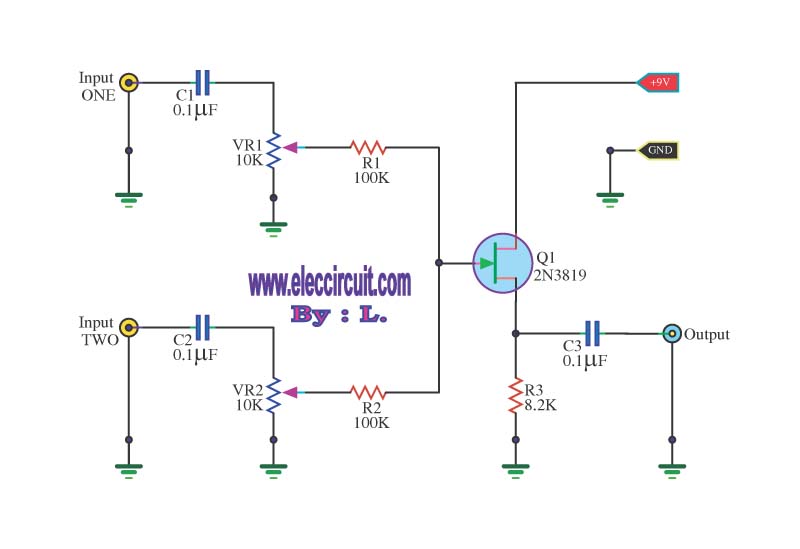
This circuit is a simple mixer circuit that can mix two signal channels into one output channel. It utilizes a codec circuit to convert stereo audio into mono audio. The circuit can also increase the number of channels by...
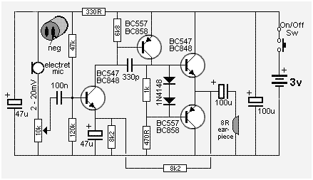
The following circuit presents a Mini Audio Amplifier Circuit Schematic Diagram. Features include a power consumption of less than 3mA, a small output, and the use of a push-pull configuration. The Mini Audio Amplifier Circuit is designed to amplify low-level...
This analyst is a sensitive instrument in the frequency changes and width of an acoustic signal. Thus, the brightness of the LED that turns on each moment is proportional to the signal width, while the color is proportional to...
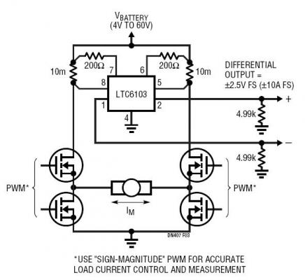
The dual outputs of the LTC6103 can be utilized independently for overload detection or combined as a differential pair to provide a bidirectional signal to an analog-to-digital converter (ADC). A typical circuit for a generic H-bridge application is illustrated....
The liquid level controller circuit comprises a power supply circuit and a level detection control circuit, as illustrated in the accompanying chart. The power supply circuit includes a power switch (S1), a power transformer (T), bridge rectifiers (UR1, UR2),...
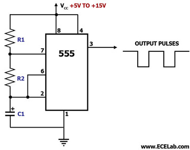
This circuit diagram illustrates the configuration of a 555 timer integrated circuit (IC) as an astable multivibrator. An astable multivibrator is a timing circuit characterized by unstable 'low' and 'high' states. Consequently, the output of an astable multivibrator continuously...