
Audio Voice-Over Circuit

This circuit design effectively integrates a microphone and preamplifier to ensure that voice communication takes precedence over other audio signals. The use of a relay as a change-over switch is a practical choice, allowing seamless transition between music playback and voice communication without audible artifacts. The BC109C transistors serve as a robust solution for the preamplifier stage, ensuring high gain and low output impedance, which are critical for maintaining audio quality over extended cable runs.
The preamplifier is designed to work optimally with an Electret Condenser Microphone, which is known for its sensitivity and low noise characteristics. The inclusion of a 100uF capacitor and a 1k resistor at the output stage is a well-considered approach to eliminate any DC offset that could interfere with the audio signal, thus preventing unwanted noise during operation.
The LM380 amplifier provides sufficient power amplification for driving speakers in various environments. The configuration allows for easy adjustment of volume levels for both the music source and the voice input, ensuring that users can tailor the audio output to their preferences. The implementation of a normally closed contact for the audio input ensures that music playback is uninterrupted until the push-to-talk function is activated, allowing for effective communication without disrupting the listening experience.
Overall, this circuit is highly suitable for remote applications, providing a reliable and efficient means of communication while minimizing interference and maintaining audio fidelity.This is a circuit where a microphone and preamp circuit (voice circuit) have priority over any other audio signal. You can think of this as a one way intercom, if the main amplifier is used for listening to music, then when the push to talk switch is pressed, the amplifier is switched to the voice signal.
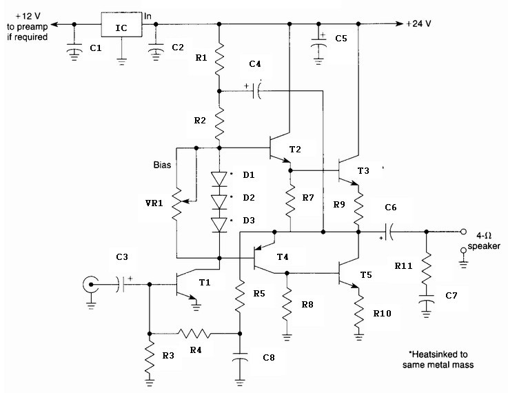
In its simplest form, a voice-over unit is just a microphone and change-over switch feeding an amplifier, the output from the microphone having priority over the amplifiers audio signal when the "push-to-talk" switch is pressed. In this circuit, a preamplifier immediately follows the microphone and is designed to be used some distance away from the main amplifier.
The changeover switch is nothing more than a relay with a single changeover contact. For completion, an amplifier based on the LM380 is shown. Three wires are needed to connect the remote microphone unit to the amplifier and switching unit. With reference to the above schematic, the two BC109C transistors are used to make a microphone preamplifier. The left hand BC109C operates in common emitter mode, the right hand emitter follower. The combination form a high gain, low output impedance amplifier, capable of driving a long audio cable.
Screened cable is not required as the output impedance from the microphone pre-amp is very low, and will be immune to mains hum and background noise. The input is shown as a three wire Electret Condenser Microphone though two wire ECM`s may also be used.
The output of the pre-amp is via a 100uF capacitor and 1k resistor. The 1k resistor here plays an important role, eliminating the dc component of the audio output. (See also eliminating the DC "thump" also on this web site. ) A cable of three or more wires is wired to the remote amplifier. The amplifier shown here is based on the National Semiconductor LM380. The input signal is passed via the normally closed contact of a changeover relay, the 10k potentiometer being the volume control for the audio input source. The 10k preset at the normally open contact allows volume control of the voice input, note that this signal has by-passed the normal volume control.
At the remote end, when the push-to-talk switch is pressed, the relay will operate and the "voice" signal will be heard in the speaker. There will be no "thump" or "thud" on voice-over as direct current has been eliminated as already mentioned.
A suitable application for this circuit would be for use in a remote location such as a workshop or shed. 🔗 External reference
Related Circuits
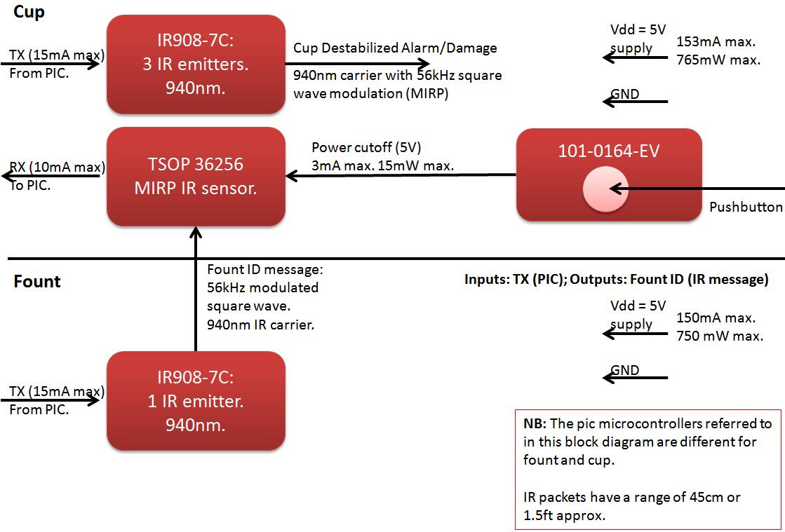
The founts must notify the server when the cup is taken from the fount or when the opponent's cup is poured into the team's cup. The implementation of the actual pouring action is at the discretion of the team....
A 10 Watt audio amplifier circuit diagram is presented. This circuit serves as a general-purpose 10-W power audio amplifier, suitable for medium power applications or for use in modulation within AM transmitters. To achieve higher power levels, up to...
The goal is to utilize a PC to measure the outdoor temperature using a serial-connected device equipped with a probe that can be conveniently placed outside. Although various options were found through online searches, many appear to be overly...
This circuit serves as a dependable alternative to thermally-activated switches designed for flashing Christmas tree lamps. The arrangement consisting of Q1, Q2, and associated resistors activates the silicon-controlled rectifier (SCR). The timing function is determined by resistors R1, R2,...
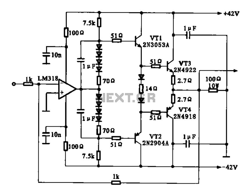
The current amplifier circuit configuration is illustrated in the figure. It consists of a two-stage operational amplifier, the LM318, arranged in a complementary push-pull amplifier configuration, which exhibits low output resistance and possesses load capacity features. The current amplifier circuit...
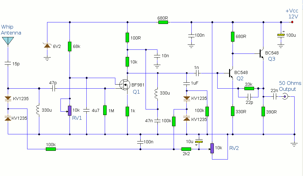
The antenna amplifier circuit comprises approximately 40 components, featuring two NPN transistors (BC548), one MOSFET (BF981), two varicap diodes (KV1235), and a 6.2V zener diode. It includes a 330µH inductor/coil, which can be modified for operation on different frequency...