
Auto touch switch

The subsequent touch on the touchplate will generate a pulse that triggers SCR1. At this point, SCR2 is turned off due to capacitor C3, which was charged by the current flowing through resistor R6 and SCR2. The activation of SCR1 applies a negative voltage across SCR2, temporarily reducing the relay current below the holding current threshold of SCR2. The holding current is defined as the minimum current required for an SCR to remain in a conductive state after its gate voltage is removed. With SCR2 deactivated, the relay opens, and SCR1 subsequently turns off due to the high resistance placed in series with its anode. This results in SCR1 being deprived of holding current, leading to its deactivation.
The circuit operates by utilizing a touch-sensitive mechanism that relies on capacitive charging and controlled triggering of SCRs to manage relay states. The interaction between the touchplate, capacitors, resistors, and SCRs allows for momentary control of the relay based on user input. When the touchplate is engaged, the system charges the capacitors and allows for the activation of the relay, while the removal of the touch interrupts the circuit, leading to the relay's deactivation. This design ensures that the relay only operates when intended, providing a reliable and user-responsive electronic control system. The inclusion of multiple components, such as resistors for current limiting and capacitors for timing, further enhances the circuit's functionality and stability.When someone touches the touchplate (TP), the resistance of his finger across points A and is added in series to the combination of Rl and R2, the capacitor C2 begins to charge. When the voltage across Cl is finally sufficient to fire NE1, Cl will begin to discharge. When NE1 fires, it produces a short between its terminals. Since R3 is connected across Cl, they are effectively in series after NE1 fires. A voltage spike will then be passed by C2 and this will act as a positive triggering pulse. The pulse is fed to both SCR gates: SCR2 conducts, thereby closing relay Kl. With a finger no longer on the touchplate, no more pulses are forthcoming because the Cl charge path is open.
The next contact with the touchplate will produce a pulse which triggers SCR1. SCR2 is now off by capacitor C3 which was charged by current passing through R6 and SCR2. The firing of SCR1 in this way places a negative voltage across SCR2 which momentarily drops the relay current to a point below the holding current value of SCR2. (Holding current is the minimum current an SCR requires to remain in a conducting state once its gate voltage is removed.) With SCR2 turned off, the relay will open and SCR1 will turn off due to the large resistance in series with its anode.
Starved in this way SCR1 turns off because of a forced lack of holding current.
Related Circuits
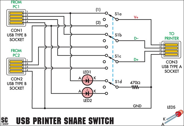
This device allows two computers to share a single USB printer or other USB devices, such as an external flash drive, memory card reader, or scanner. A rotary switch is used to select the PC that will use the...
This is a three-mode lamp dimmer circuit with touch control. This circuit can be used to control a lamp in three operation modes: dim, off, and bright. A NE555 timer is utilized in the design. The three-mode lamp dimmer circuit...
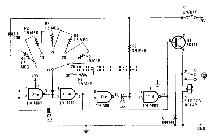
The circuit is constructed using a 4001 quad two-input NOR gate, allowing for switch-selectable auto-advance times of 5, 10, 15, 20, 25, or 30 seconds through the remote control socket of a projector. Ula and Ulb create an astable...
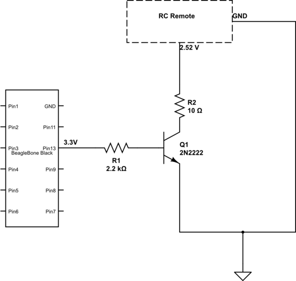
The remote control of an RC car was modified by extending wires from the backward, forward, left, and right switches. Grounding any of these wires completes the circuit and sends a signal to the car. The intention is to...
Flicker-free updating of analog input and the status of switches using Ajax and the Arduino Ethernet Shield. The Arduino Uno is configured as a web server. The described system utilizes an Arduino Uno microcontroller, which operates as a web server...
This is an automatic LCD panel backlight control circuit. It is a simple, low-cost implementation of an LED controller that can compensate for aging effects. The automatic LCD panel backlight control circuit is designed to enhance the performance and longevity...