
Automatic headlight dim switch

This headlight control circuit offers a practical solution for enhancing nighttime driving safety by automatically adjusting the beam intensity based on surrounding traffic conditions. The core components include a phototransistor (Q1) that is sensitive to light changes, allowing it to detect when an oncoming vehicle approaches. The phototransistor's response to light is crucial; when illuminated by the headlights of an approaching vehicle, Q1 conducts, leading to increased current flow.
Transistor Q2 (BC177) functions as a switch in this configuration. It is connected to the relay that controls the headlight power. When Q1 is activated by light, it allows current to flow into the base of Q2, thereby turning it on. This action energizes the relay, which interrupts the high beam circuit and dims the headlights to low beam, reducing glare for oncoming drivers.
Once the oncoming vehicle passes and the light source is no longer detected by Q1, the circuit resets. The reduced light on Q2 causes it to turn off, which deactivates the relay, allowing the headlights to return to high beam. This automatic switching enhances driving comfort and safety by ensuring that high beams are only used when appropriate.
For optimal performance, the circuit should be designed with appropriate resistor values to ensure that both Q1 and Q2 operate within their specified ranges. Additionally, the relay must be rated to handle the current load of the vehicle's headlights. Proper placement of the phototransistor is also critical; it should be positioned to effectively capture the light from oncoming vehicles while being shielded from ambient light sources that could cause false triggering. This system not only improves visibility for the driver but also contributes to the overall safety of nighttime driving.With this cool circuit integrated to your cars headlight system, you can drive cool headed in high beam. The circuit will take over the duty of low beaming the headlight when vehicles approach against, and high beams the lights when they pass over.
The circuit is based on a photo transistor(Q1) for sensing the approaching vehicles and transistor Q2 (BC177) for switching the relays for controlling the headlight. When the light from the opposite vehicle falls on Q2, it`s collector current increases and turns ON Q1. The relay will be activated and the head light will be dimmed. When the vehicle pass over the reverse will happen. 🔗 External reference
Related Circuits
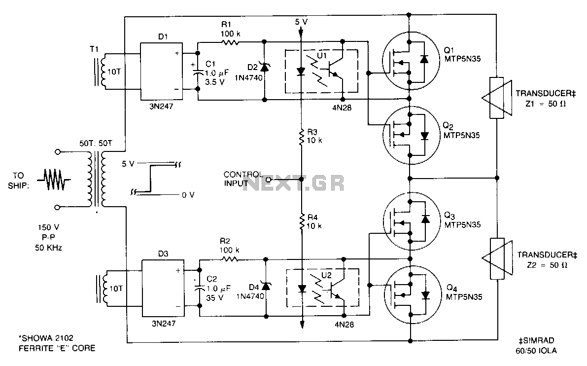
This submersible sonar positioning apparatus primarily comprises dual-opposed ultrasonic transducers that are alternately excited, with the return signals processed and displayed for observation and measurement. Typical transmitter frequencies range from 50 to 200 kHz, and pulse widths can be...

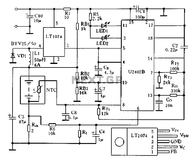
Low power 5V switching regulator power supply. Visit the corresponding page for an explanation of the related circuit diagram. The low power 5V switching regulator is designed to efficiently convert a higher input voltage to a stable 5V output while...
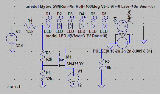
A suitable method to sense when some LEDs in a garage door opener are illuminated. A power source, potentially the same as Vout, connects to a 1.5 kΩ resistor, which then connects to six LEDs followed by a transistor....
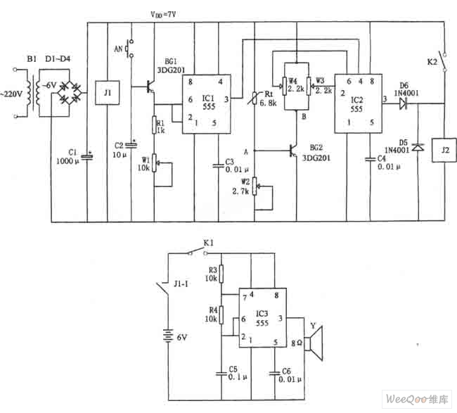
The figure illustrates the automatic watering control circuit for bean sprouts. The controller includes a step-down rectifier circuit, a power outage detection component (IC3), a timing control circuit (IC1), and a temperature control circuit (IC2). The step-down rectifier circuit...

This discussion focuses on headlamp dimmer-controlled fog lamps within the Ford Raptor Lighting Modifications Forum, part of the Ford Raptor Forums - Modifications category. For those interested in installing fog lamps that can be controlled by the dimmer switch...
Charging circuit from the DC power supply switching power supply control The charging circuit described is designed to operate with a DC power supply, utilizing a switching power supply control mechanism. This type of circuit is commonly employed in applications...