
Automatic ttl morse-code keyer

The described circuit is designed to generate Morse code signals, represented as "dits" (short signals) and "dahs" (long signals), at adjustable speeds ranging from 11 to 39 words per minute (wpm). The speed of the generated signals can be modified by adjusting the resistance of resistor R2. By decreasing the resistance value of R2, the circuit can achieve a higher transmission speed, thus allowing for more rapid generation of Morse code.
The keying mechanism is facilitated by two switches, SW1 and SW2, which can be implemented as a homebrew paddle key. This type of key allows the operator to manually control the generation of dits and dahs by pressing one switch for a short signal and another for a long signal. The paddle design provides a user-friendly interface for Morse code transmission, enabling efficient and precise operation.
In a typical schematic, the circuit may include additional components such as capacitors for signal smoothing, diodes for protection against reverse polarity, and possibly a microcontroller to manage timing and signal generation. The output can be connected to an audio oscillator or a radio transmitter, enabling the Morse code signals to be transmitted over radio frequencies or converted to audible tones.
Overall, this circuit presents a versatile solution for generating Morse code, suitable for both hobbyists and professionals interested in amateur radio and communication technologies.Automatically generated dits and dahs are produced over a speed range of 11 to 39 wpm. The upper limit can be raised by decreasing R2 SWl and SW2 can be a "homebrew" paddle operated key.
Related Circuits
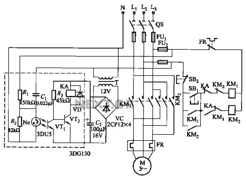
In certain applications, it is crucial to allow a motor to operate in only one specific direction, even when the power supply phase sequence is incorrect. This situation may arise due to external factors, such as incorrect wiring after...

The phase and neutral wires from the power source have already been connected to electrical appliances such as fans and light points. According to the UPS connection diagram, an additional phase wire should be connected to those appliances where...
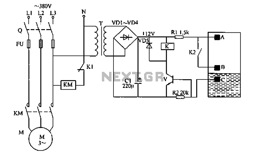
The liquid level automatic controller circuit consists of a power circuit, a level detection circuit, and a control implementation circuit. The power circuit is formed by a power transformer T, rectifier diodes YD1 to VD4, and a filter capacitor...
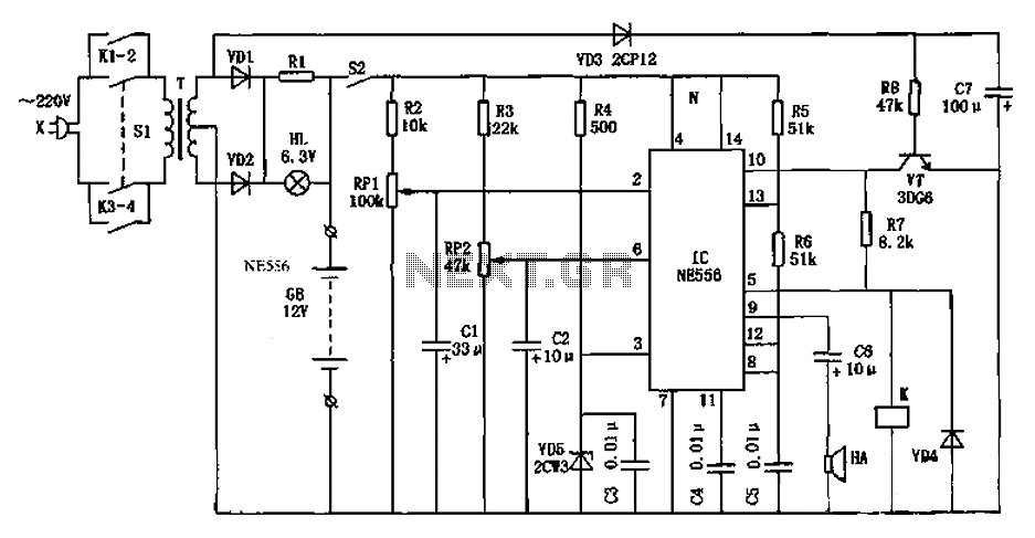
As shown in the generator start battery automatic monitor circuit diagram. The generator start battery automatic monitor circuit is designed to oversee the battery's status during generator operation. This circuit ensures that the battery remains charged and functional, preventing premature...
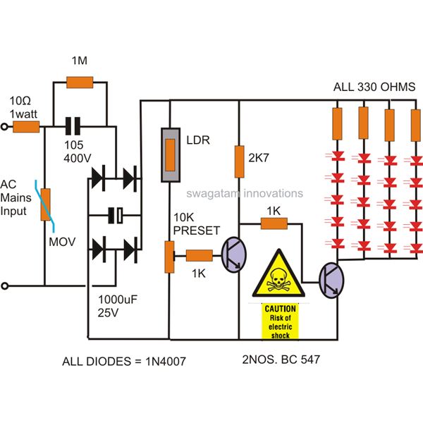
The power supply utilized in this circuit is of the capacitive type, eliminating the need for a transformer and allowing for a compact design that can be easily installed in small spaces. The circuit employs LEDs instead of traditional...
New applications for DC voltage converters, such as the LT1070, arise every day. These converters can be adapted to nearly every imaginable ratio of input and output voltages. However, all of these circuits and devices share a common shortcoming:...